Charge control device and load driving device

a technology of charge control device and load driving device, which is applied in the direction of electric variable regulation, process and machine control, instruments, etc., can solve the problems of the same problem occurring in the load driving device, the risk of a current being larger than the current,

Active Publication Date: 2011-09-22
ROHM CO LTD
View PDF3 Cites 12 Cited by
  • Summary
  • Abstract
  • Description
  • Claims
  • Application Information

AI Technical Summary

Benefits of technology

[0012]The disclosure describes a charge control device and a load driving device that in some implementation

Problems solved by technology

Thus, there is a risk of a current larger than a predetermined value flowing through the secondary battery BAT.
In the foregoing description, although a charge control device is il

Method used


Image

  • Charge control device and load driving device
  • Charge control device and load driving device
  • Charge control device and load driving device

Examples


Embodiment Construction

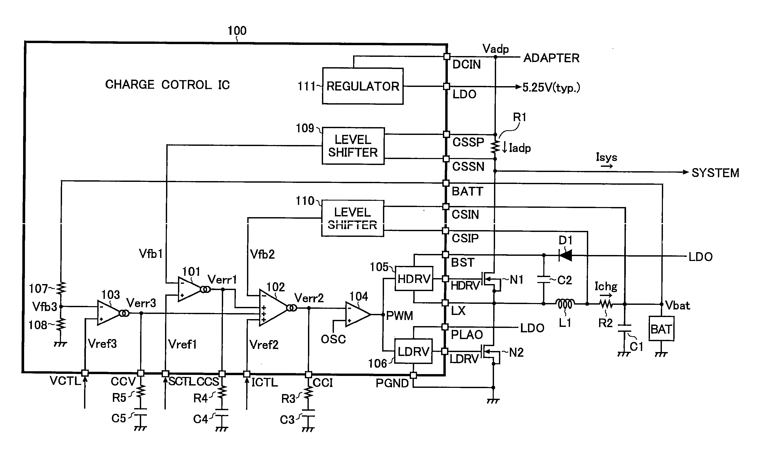
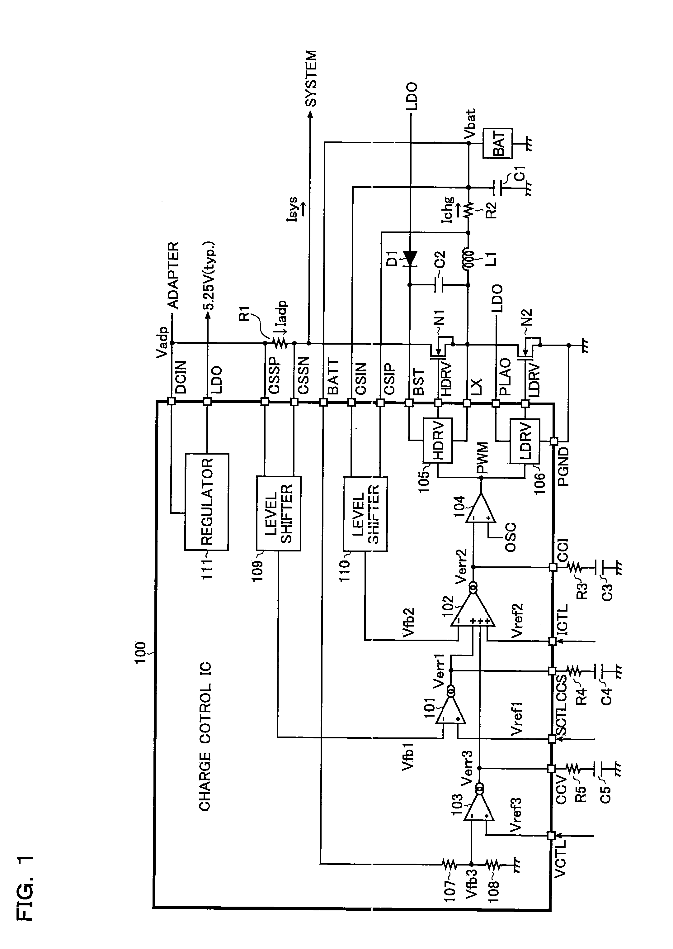
[0027]As illustrated in FIG. 1, a charge control IC 00 includes a first error amplifier 101, a second amplifier 102, a third error amplifier 103, a PWM (Pulse Width Modulation) comparator 104, an upper side driver 105, a lower driver 106, resistors 107 and 108, level shifters 109 and 110, and a regulator 111. These elements can be integrated. The charge control IC 100 is equipped for an electrical apparatus (e.g., a lap top PC).

[0028]The charge control IC 100 includes a DCIN terminal (a power supply terminal), a LDO terminal (an internal power supply terminal[5.2V]), a CSSP terminal (a primary current detection terminal[+]), a CSSN terminal (a primary current detection terminal[−]), a BATT terminal (a battery voltage monitor terminal), a CSIN terminal (a charge current detection terminal[−]), a CSIP terminal (a charge current detection terminal[+]), a BST terminal (a step-up terminal to drive a high side MOS FET), a HDRV terminal (an output terminal of a high side MOSFET), a LX term...


PUM


Abstract

A charge control device includes a charge control circuit to control a charge of a secondary battery by controlling an output stage connected between a power supply and the secondary battery. The charge control circuit includes a first error amplifier to generate a first error voltage in response to a difference between a predetermined first reference voltage and a first feedback voltage. The value of the first feedback voltage is determined in accordance with a primary current supplied from the power supply to the output stage. The charge control circuit also includes a second error amplifier to generate a second error voltage in response to a difference between either one of a predetermined second reference voltage and the first error voltage, and a second feedback voltage. The value of the second feedback voltage is determined in accordance with a charge current supplied from the output stage to the secondary battery. The charge control circuit also includes a control signal generator to generate the control signal of the output stage in response to the second error voltage.

Description

CROSS-REFERENCE TO RELATED APPLICATIONS[0001]This application claims the benefit of priority of Japanese patent application No. 2010-062973 (filing date: 2010 Mar. 18), which is incorporated herein by reference in its entirety.BACKGROUND[0002]1. Field of the Invention[0003]This disclosure relates to a charge control device or a load driving device that have a constant current control function for a charge current or a driving current.[0004]2. Description of Related Art[0005]FIG. 6 shows a charge control device in accordance with the related art. The charge control device includes a first feedback loop to perform a constant current control on an adaptor current Iadp supplied from an adaptor, a second feedback loop to perform a constant current control on a charge current Ichg supplied to a secondary battery BAT, and a third feedback loop to perform a constant voltage control on a charge voltage Vbat supplied to a secondary battery EAT. These feedback loops are connected in parallel. ...

Claims


Application Information

Patent Timeline
IPC IPC(8): H02J7/04G05F1/10
CPCH02J7/045H01M2010/4271Y02E60/10H02J7/04H02J7/00714H02J7/007182
Inventor AKAHO, TADASHI
Owner ROHM CO LTD
Why Eureka
Try Eureka