Distributed optical fiber sensor

a technology of optical fiber and optical fiber, applied in the direction of instruments, heat measurement, optical apparatus testing, etc., can solve the problem of not being able to measure strain and temperature separately and simultaneously, and achieve the effect of high spatial resolution

Active Publication Date: 2011-09-22
NEUBREX
View PDF15 Cites 80 Cited by
  • Summary
  • Abstract
  • Description
  • Claims
  • Application Information

AI Technical Summary

Benefits of technology

[0017]Thus, the distributed optical fiber sensor according to the present invention can measure the strain and temperature of a test object simultaneously and independently with high spatial resolution.

Problems solved by technology

Nevertheless, since the Brillouin frequency shift amount that is measured using the Brillouin scattering phenomenon changes depending on the two parameters of strain and temperature of the optical fiber, the parameter that can be measured using the Brillouin scattering phenomenon is basically one of either the strain or temperature, and it is not possible to separately and simultaneously measure the strain and temperature.

Method used


Image

  • Distributed optical fiber sensor
  • Distributed optical fiber sensor
  • Distributed optical fiber sensor

Examples


Embodiment Construction

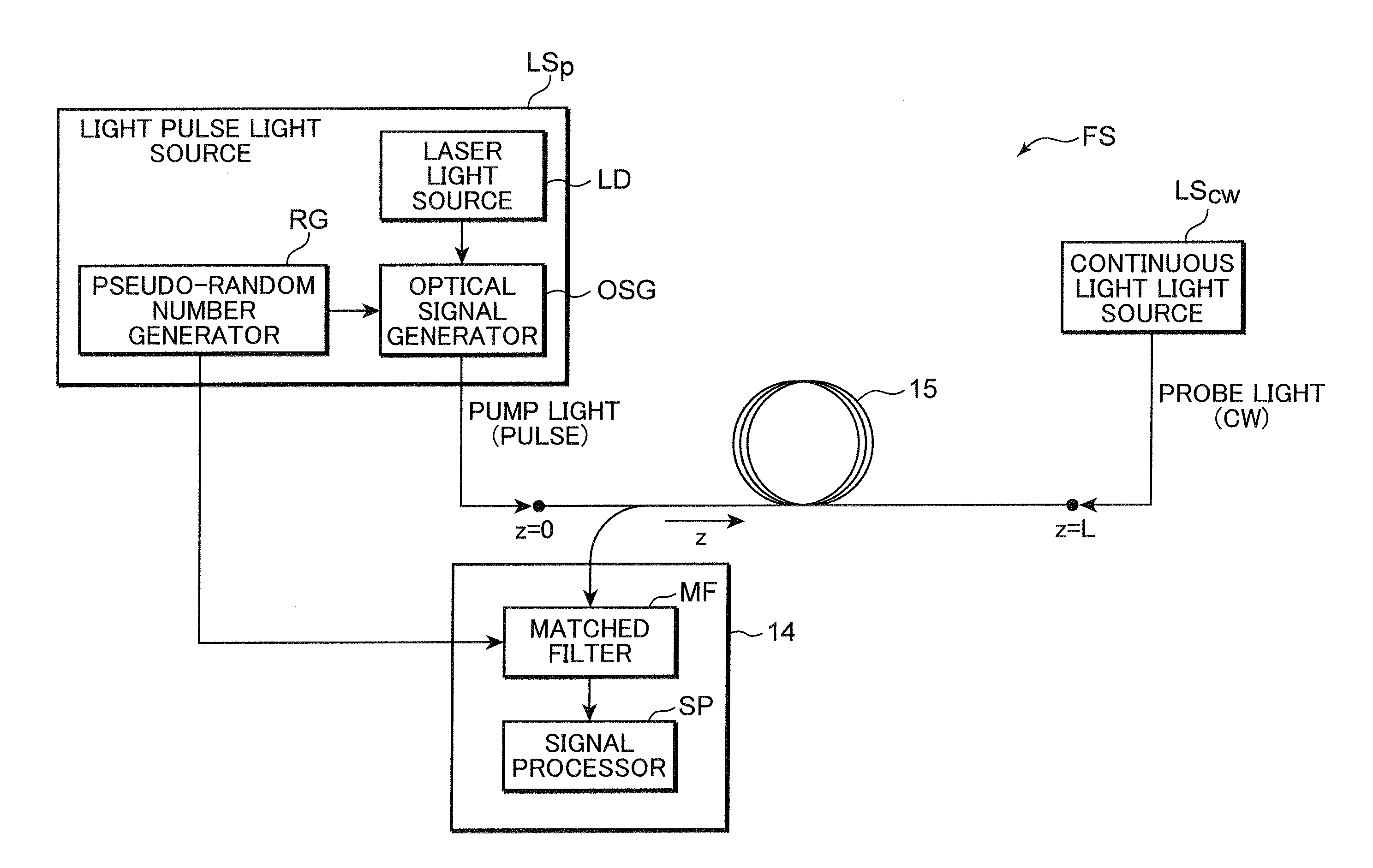
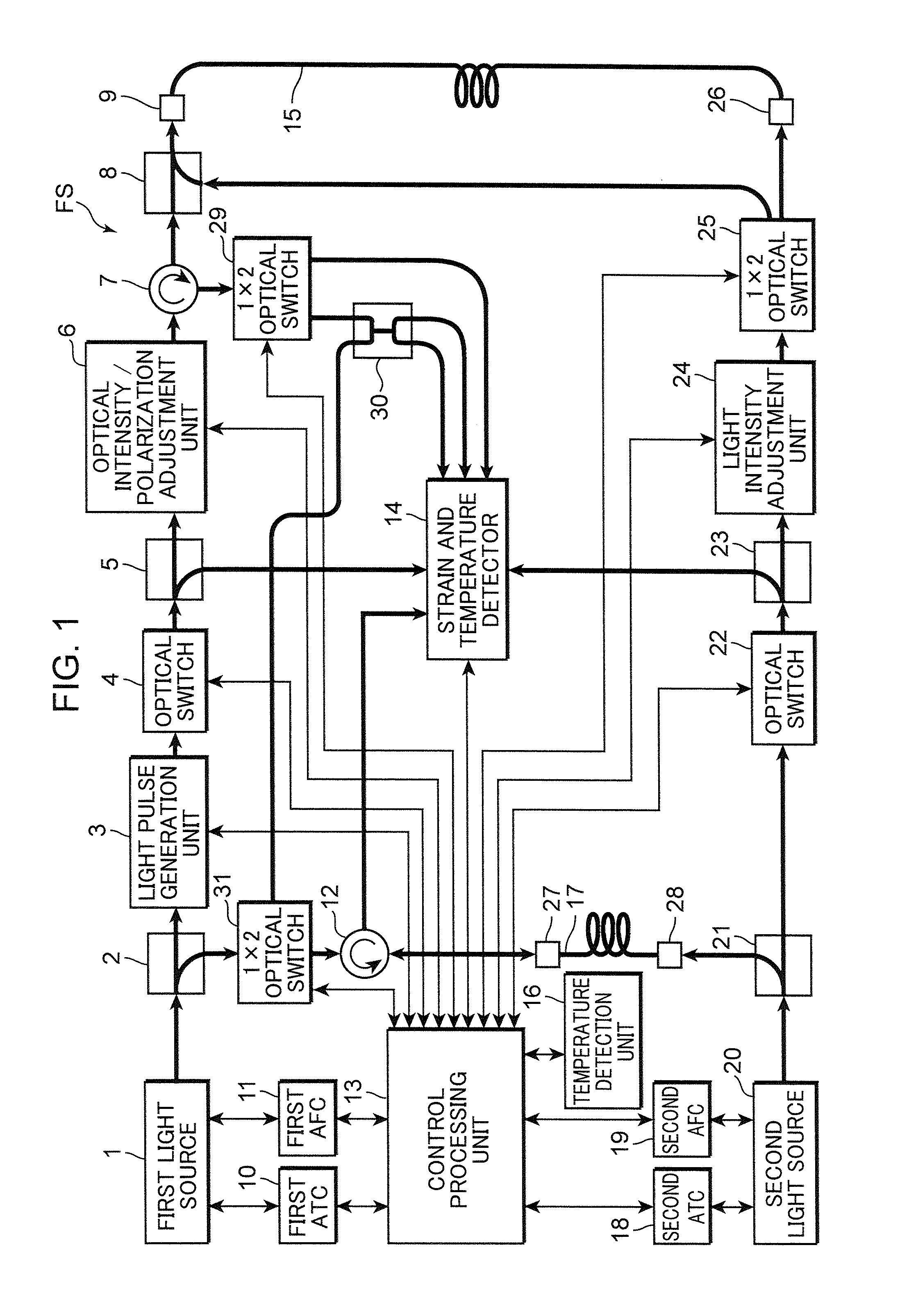
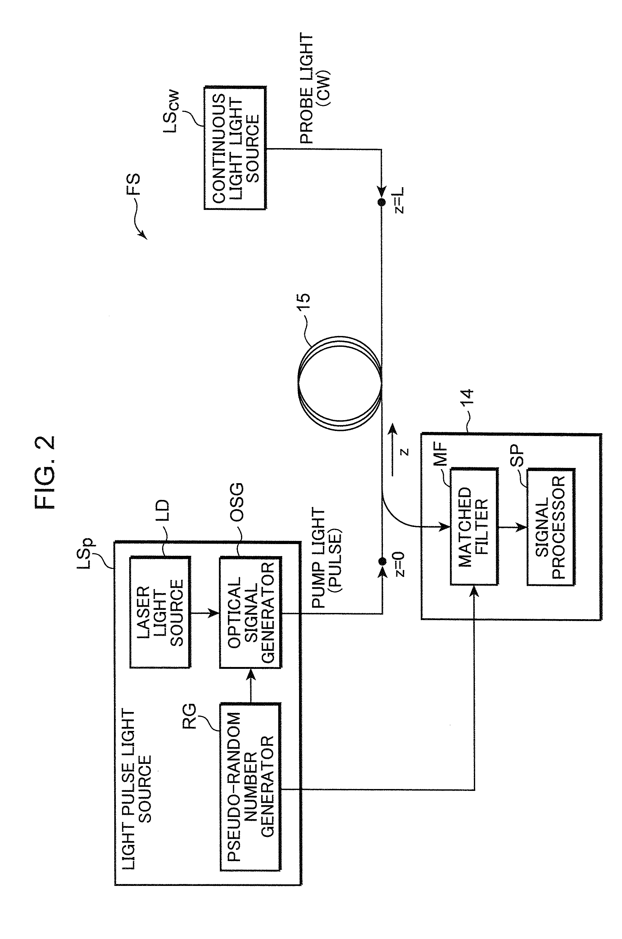
[0047]The first embodiment of the distributed optical fiber sensor according to the present invention is now explained with reference to the appended drawings. Note that the configuration given the same reference numeral in the respective drawings shows that it is the same configuration, and the explanation thereof is omitted. FIG. 1 is a block diagram showing the configuration of the distributed optical fiber sensor in the first embodiment.

[0048]A distributed optical fiber sensor FS shown in FIG. 1 includes a first light source 1, optical couplers 2, 5, 8, 21, 23, 30, a light pulse generation unit 3, optical switches 4, 22, an optical intensity / polarization adjustment unit 6, optical circulators 7, 12, optical connectors 9, 26, 27, 28, a first automatic temperature control unit (hereinafter referred to as the “first ATC”) 10, a first automatic frequency control unit (hereinafter referred to as the “first AFC”) 11, a control processing unit 13, a strain and temperature detector 14, ...


PUM

PropertyMeasurementUnit
line widthaaaaaaaaaa
Brillouin frequencyaaaaaaaaaa
temperatureaaaaaaaaaa

Abstract

The present invention provides a distributed optical fiber sensor capable of measuring the strain and temperature of an object to be measured simultaneously and independently with high spatial resolution. A distributed optical fiber sensor FS is a distributed optical fiber sensor which uses an optical fiber 15 as a sensor, and a strain and temperature detector 14 measures a Brillouin frequency shift amount caused by a strain and a temperature generated in the optical fiber 15 by using a Brillouin scattering phenomenon, measures a Rayleigh frequency shift amount caused by the strain and temperature generated in the optical fiber 15 by using a Rayleigh scattering phenomenon, and calculates the strain and temperature generated in the optical fiber 15 from the measured Brillouin frequency shift amount and Rayleigh frequency shift amount.

Description

BACKGROUND OF THE INVENTION[0001]1. Field of the Invention[0002]The present invention relates to a distributed optical fiber sensor which uses an optical fiber as a sensor, and which is capable of measuring the strain and temperature in the longitudinal direction thereof with high precision.[0003]2. Description of the Related Art[0004]Conventionally, as technology of measuring the strain and temperature, there is a method based on the Brillouin scattering phenomenon which occurs in the optical fiber. In this method, the optical fiber is used as the medium from which the strain and / or temperature is to be detected in the environment (object to be measured) where such optical fiber is to be installed.[0005]The Brillouin scattering phenomenon is a phenomenon where power travels via the acoustic phonon in the optical fiber when light enters the optical fiber, and there are the stimulated Brillouin scattering phenomenon which occurs as a result of two lights with mutually different frequ...

Claims


Application Information

Patent Timeline
Patent Type & Authority Applications(United States)
IPC IPC(8): G01B11/16G01D5/353G01K11/00
CPCG01B11/18G01K11/32G01K2011/322G01M11/083G01L1/242G01N21/21G01D5/35364G01B11/168G01K11/322
Inventor LI, CHE-HSIENKISHIDA, KINZONISHIGUCHI, KENICHIGUZIK, ARTURMAKITA, ATSUSHIYAMAUCHI, YOSHIAKI
Owner NEUBREX
Why Eureka
Try Eureka