Eureka AIR delivers breakthrough ideas for toughest innovation challenges, trusted by R&D personnel around the world.

High Bandwidth Programmable Transmission Line Pre-Emphasis Method and Circuit

Active Publication Date: 2011-09-22
MICREL
View PDF32 Cites 9 Cited by
  • Summary
  • Abstract
  • Description
  • Claims
  • Application Information

AI Technical Summary

Benefits of technology

[0004]According to one embodiment of the present invention, a transmission line pre-emphasis circuit includes a primary signal path coupled to receive a digital data stream to be transmitted and provide a primary output current indicative of the digital data stream to a pair of current summing nodes, one or more secondary signal paths each incorporating a network implementing a specific transient response where the one or more secondary signal paths receive the digital data stream and generate secondary output currents representing one or more overshoot signals indicative of the transient response of

Problems solved by technology

Most of these media exhibit signal loss as the data signal is transmitted over the length of the transmission line and that signal loss increases with line length and signal harmonic frequencies.
That is, the higher frequency components of the data signal being carried is more susceptible to signal loss for long line length.
Because the high frequency components of a digital bit stream defines the transition edges of the data signal, losing the high frequency components of the data signal results in distortion.
Severe distortion can introduce errors into the received bit stream.
In some instances, the limit of equalization is reached and equalization alone cannot fully recover the original data stream and other compensation methods are desired.

Method used


Image

  • High Bandwidth Programmable Transmission Line Pre-Emphasis Method and Circuit
  • High Bandwidth Programmable Transmission Line Pre-Emphasis Method and Circuit
  • High Bandwidth Programmable Transmission Line Pre-Emphasis Method and Circuit

Examples


first embodiment

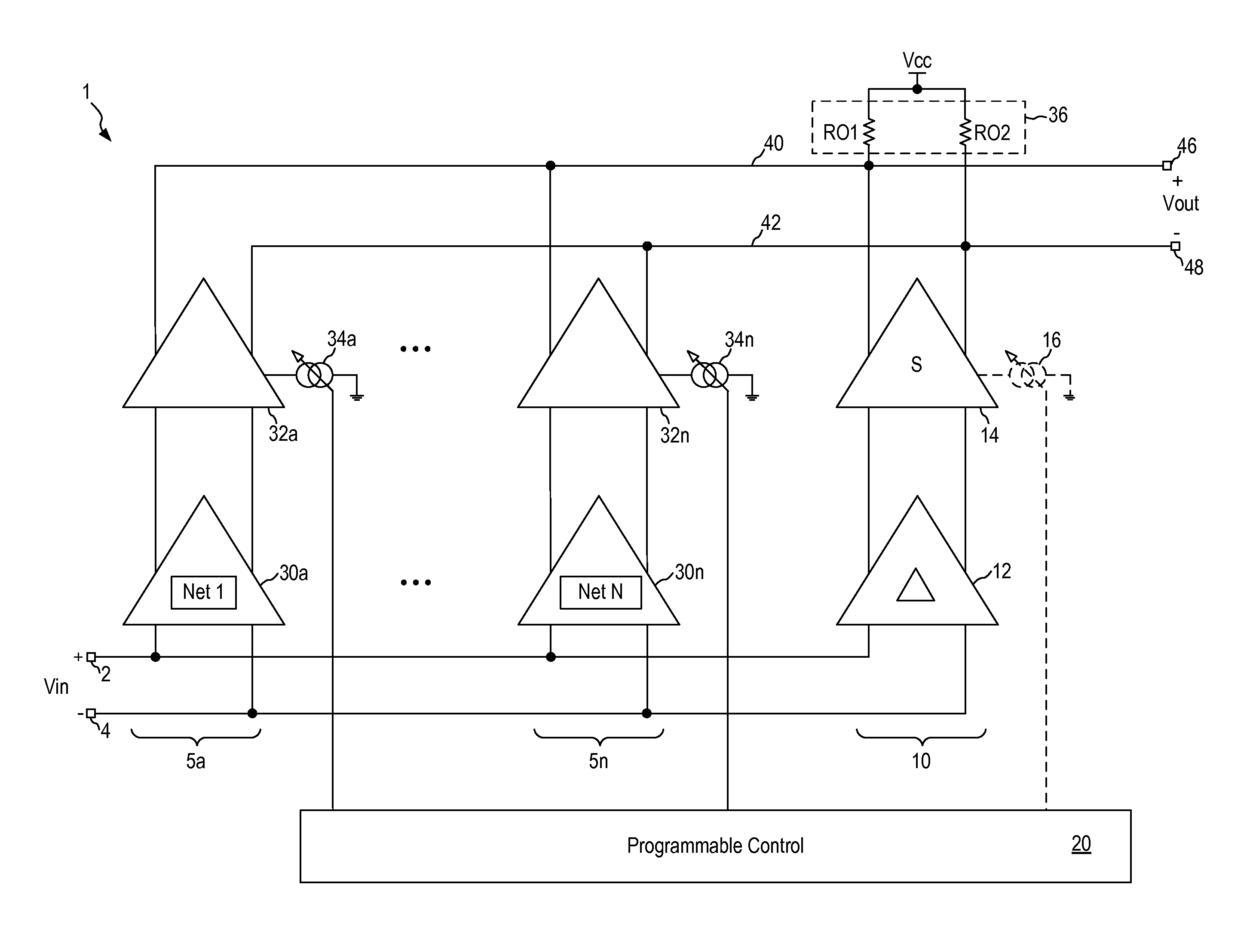
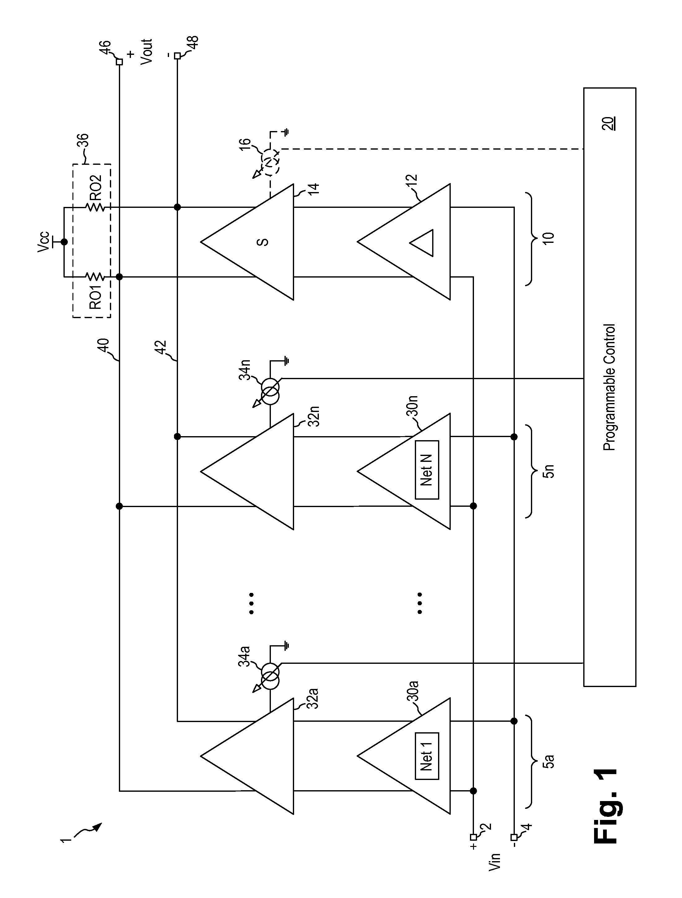
[0024]FIG. 1 is a schematic diagram of a transmission line pre-emphasis circuit according to the present invention. Referring to FIG. 1, a transmission line pre-emphasis circuit 1 (“pre-emphasis circuit 1”) receives a differential digital input signal Vin on a pair of differential input terminals 2, 4. Digital input signal Vin represents the digital data stream to be transmitted onto the transmission line. Input signal Vin is a digital bit stream with fast rise and fall time and may be described as a series of step functions that comprise a digital bit stream. Transmission line pre-emphasis circuit 1 generates a pre-emphasized differential output signal Vout on a pair of differential output terminals 46, 48. Transmission line pre-emphasis circuit 1 includes a primary signal path 10 for passing the digital input signal Vin and one or more secondary signal paths 5a to 5n. Each of the secondary signal paths incorporates one or more unique networks (Net 1 to Net N) to implement specific...

second embodiment

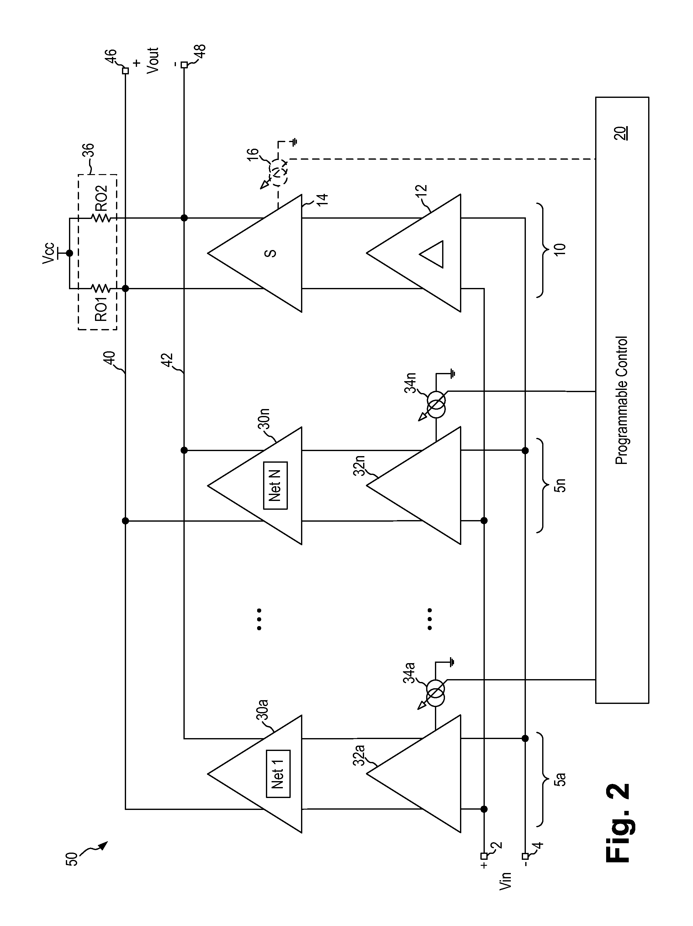
[0036]In the pre-emphasis circuit shown in FIG. 1, the secondary signal paths are constructed using the first stage amplifiers as the wave shaping stage and the second stage amplifiers as the gain stage or amplification stage. In other embodiments, the arrangement of the wave shaping stage and the gain stage can be varied. FIG. 2 is a schematic diagram of a transmission line pre-emphasis circuit according to the present invention. Referring to FIG. 2, transmission line pre-emphasis circuit 50 is constructed in the same manner as pre-emphasis circuit 1 of FIG. 1 and like elements are given like reference numerals and will not be further described. In transmission line pre-emphasis circuit 50, the first stage amplifiers 32a-n are implemented as gain stages and the second stage amplifiers 30a-n are implemented as wave shaping stages. Pre-emphasis circuit 50 operates in the same manner as pre-emphasis circuit 1 to generate a pre-emphasis output voltage incorporating transient responses ...


PUM


Abstract

A transmission line pre-emphasis circuit includes a primary signal path receiving a digital data stream and generating a primary output current indicative of the digital data stream, one or more secondary signal paths each incorporating a network implementing a specific transient response where the one or more secondary signal paths receive the digital data stream and generate secondary output currents representing one or more overshoot signals indicative of the transient response of the respective network. The one or more secondary signal paths have variable gain being programmed through respective DC programming signals. The secondary output currents are summed with the primary output current. The transmission line pre-emphasis circuit further includes an output loading stage coupled to generate from the summed current a pre-emphasized digital output signal indicative of the one or more overshoot signals added to the digital data stream.

Description

FIELD OF THE INVENTION[0001]The invention relates to transmission line pre-emphasis circuit and method and, in particular, to a programmable transmission line pre-emphasis circuit and method for use in high bandwidth applications.DESCRIPTION OF THE RELATED ART[0002]High digital data rates often mandate using properly terminated, controlled impedance paths, called transmission lines, to maintain data integrity. Transmission lines can include a variety of media, such as coaxial cables, twinax cables, as well as single traces and differential pair traces on a PC board such as striplines, microstrip lines and coplanar waveguides. Most of these media exhibit signal loss as the data signal is transmitted over the length of the transmission line and that signal loss increases with line length and signal harmonic frequencies. That is, the higher frequency components of the data signal being carried is more susceptible to signal loss for long line length. Because the high frequency component...

Claims


Application Information

Patent Timeline
IPC IPC(8): H04B3/00H04B1/38
CPCH04B3/141
Inventor LUTZ, ROBERT C.WONG, THOMAS S.PIONTEK, KLAUS P.
Owner MICREL
Why Eureka
Eureka Blog
Learn More