Electret Microphone Circuit

Active Publication Date: 2011-09-22
LOGITECH EURO SA
View PDF15 Cites 7 Cited by
  • Summary
  • Abstract
  • Description
  • Claims
  • Application Information

AI Technical Summary

Problems solved by technology

Variations of the voltage between the source and drain of FET Q1 will cause corresponding changes in the parasitic capacitances within FET Q1, which may contribute to distortion of the amplified signal.
Additionally, since parasitic gate-source capacitance of the FET Q1 may vary nonlinearly with volt

Method used


Image

  • Electret Microphone Circuit
  • Electret Microphone Circuit
  • Electret Microphone Circuit

Examples


Embodiment Construction

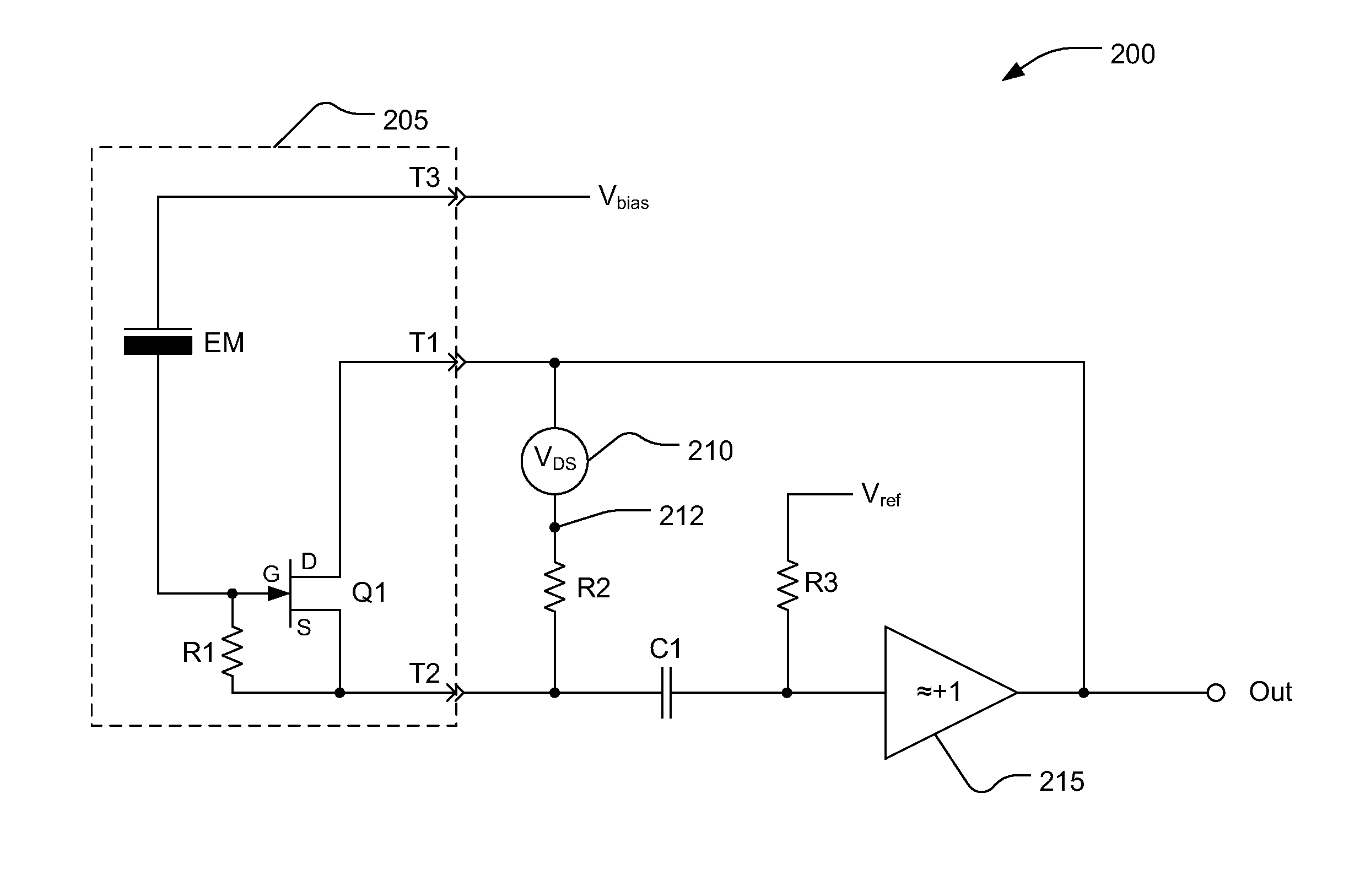
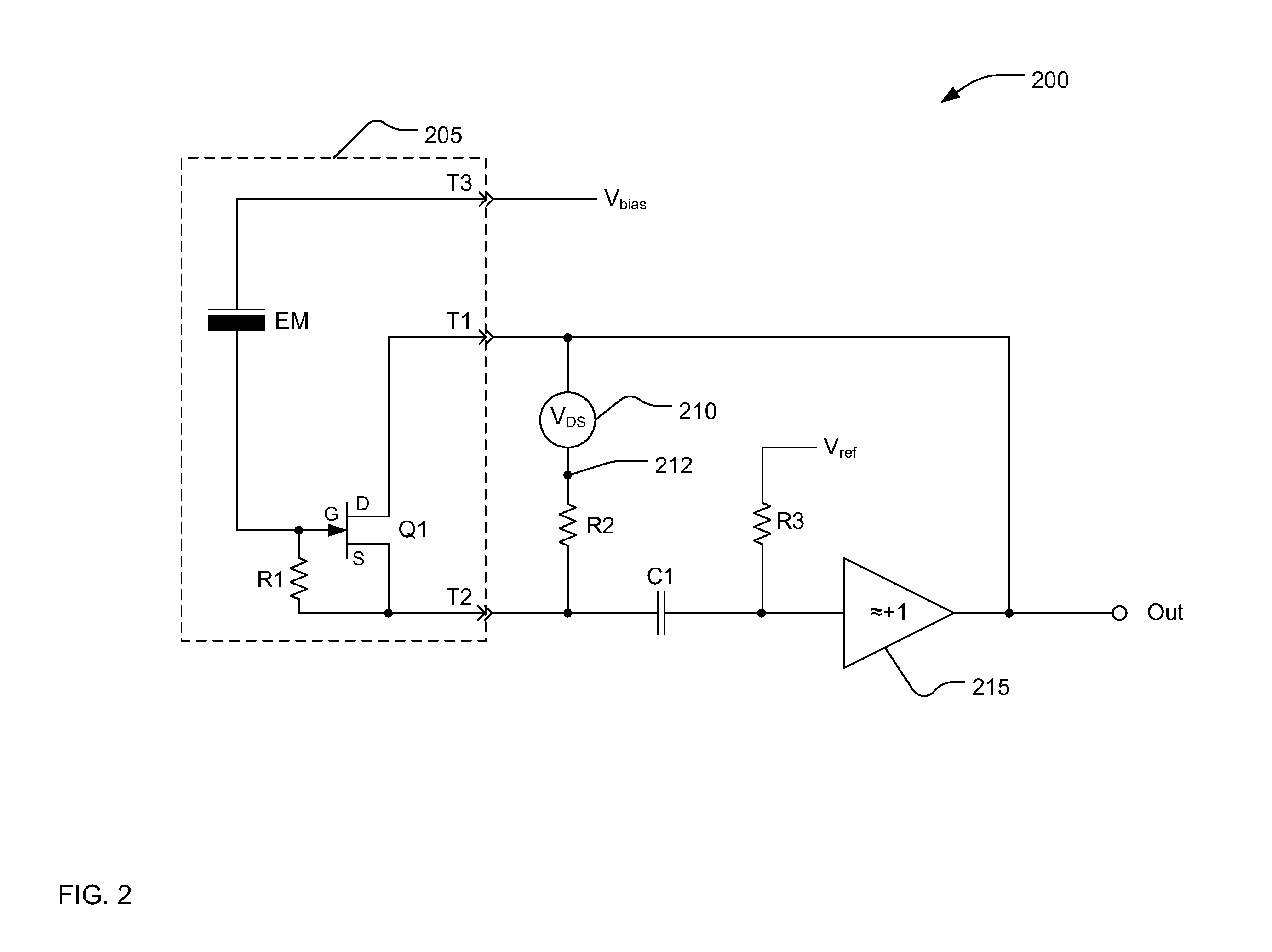
[0019]Referring now to FIG. 2, an electret microphone circuit 200 may include a three-terminal electret microphone capsule 205, which may be the electret microphone capsule 105. A voltage source 210 in series with a resistor R2 may be connected from terminal T1 to terminal T2 of the electret microphone capsule 205. A first end of the voltage source 210 may be connected to terminal T1 of the electret microphone capsule 205. A second end of the voltage source 210 may be connected to a first end of the resistor R2 at a node 212. A second end of resistor R2 may be connected to terminal T2 of the electret microphone capsule 205. Note that, if the node 212 between the voltage source 210 and the resistor R2 was grounded, the FET Q1 within the electret microphone capsule would be operating as source follower as shown in FIG. 1B. In the circuit of FIG. 2, however, the voltage source is floating with respect to ground potential. In this context, the term “floating” means that the node 212 is ...


PUM


Abstract

There is disclosed a microphone, a circuit, and a method. A microphone capsule may include an electret microphone and a field effect transistor (FET). A floating DC voltage source may have a first end connected to a drain terminal of the electret microphone capsule and a second end. A load resistor may be connected between the second end of the floating DC voltage source and a source terminal of the electret microphone capsule. A voltage follower may have an output connected to the source terminal of the electret microphone capsule and the first end of the floating DC voltage source. A coupling capacitor may couple an audio signal from the source terminal of the electret microphone capsule to an input of the voltage follower.

Description

NOTICE OF COPYRIGHTS AND TRADE DRESS[0001]A portion of the disclosure of this patent document contains material which is subject to copyright protection. This patent document may show and / or describe matter which is or may become trade dress of the owner. The copyright and trade dress owner has no objection to the facsimile reproduction by anyone of the patent disclosure as it appears in the Patent and Trademark Office patent files or records, but otherwise reserves all copyright and trade dress rights whatsoever.BACKGROUND[0002]1. Field[0003]This disclosure relates to microphones for converting acoustic waves to electrical signals, and specifically to high performance microphone systems using electret microphones.[0004]2. Description of the Related Art[0005]An electrostatic microphone, also commonly called a condenser microphone, contains a fixed plate and a flexible diaphragm that collectively form a parallel plate capacitor. The diaphragm moves in response to incident acoustic wa...

Claims


Application Information

Patent Timeline
IPC IPC(8): H04R3/00
CPCH04R19/016H04R3/00
Inventor SAULESPURENS, MARTINSSTANEVICS, FELIKSS
Owner LOGITECH EURO SA
Why Eureka
Try Eureka