Toner dispersing member and toner dispersing mechanism provided therewith
- Summary
- Abstract
- Description
- Claims
- Application Information
AI Technical Summary
Benefits of technology
Problems solved by technology
Method used
Image

Examples
first embodiment
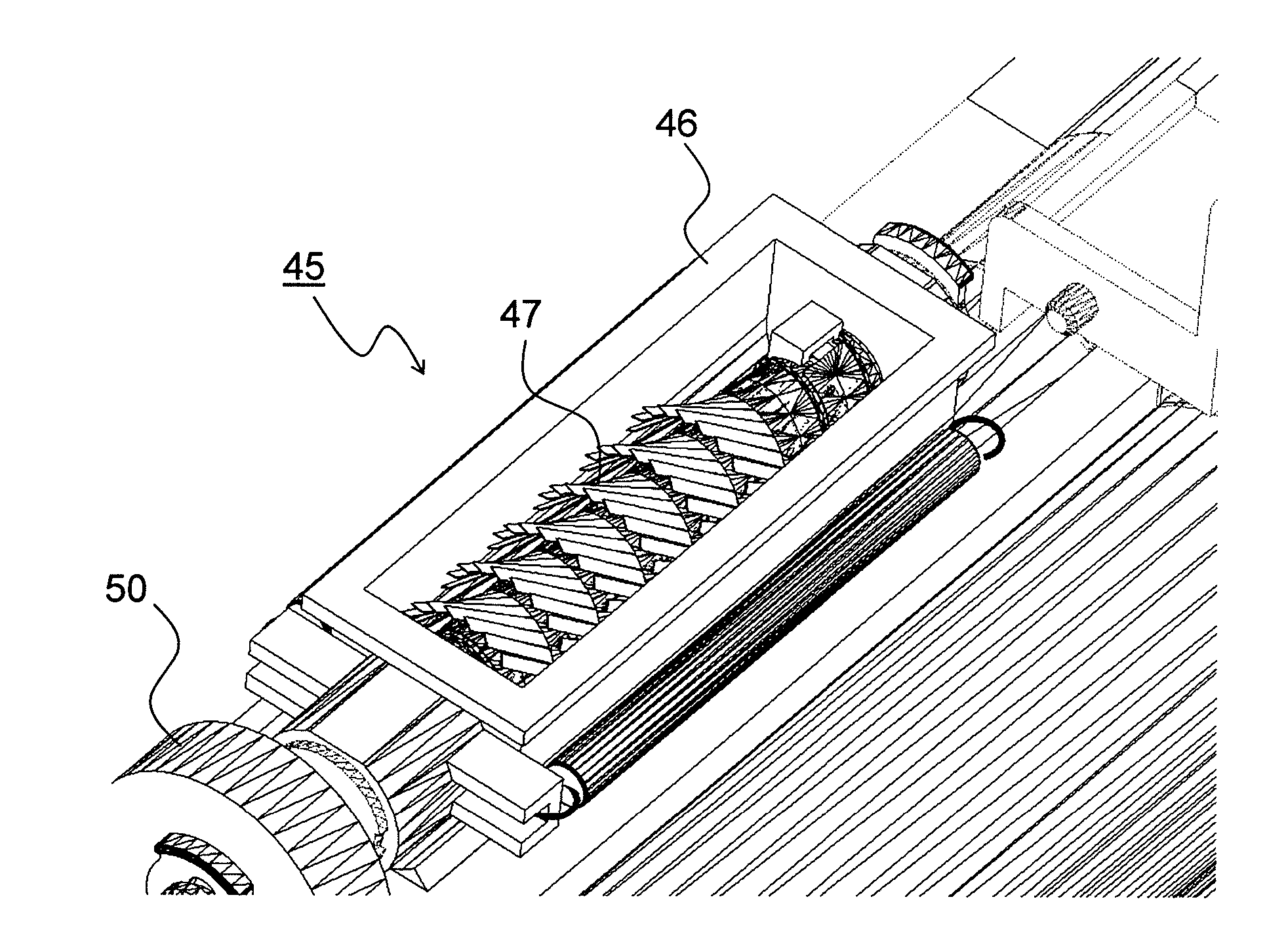
[0055]FIG. 6 is a developed view of the dispersing protrusions used for the toner dispersing member according to the present invention, and FIG. 7 is a perspective view of the toner dispersing member constituted by the dispersing protrusions of FIG. 6 helically wound about the rotary shaft. In the toner dispersing member 47 in this embodiment, a ribbon-like film member 51 has a large number of cuts 53 formed on one side in the longitudinal direction (upper side of FIG. 6), and a fixation portion 54 includes a part which is free from the cuts 53, and the dispersing protrusions 47b are constituted by the cuts 53 directed outward and the film member 51 helically wound along an outer peripheral surface of the rotary shaft 47a.
[0056]As illustrated in FIG. 6, the cuts 53 are formed not perpendicularly but diagonally with respect to a longitudinal direction of the film member 51. With this, when the film member 51 is wound along the outer peripheral surface of the rotary shaft 47a, the pa...
second embodiment
[0061]FIG. 9 is a developed view of the dispersing protrusions used for the toner dispersing member according to the present invention, and FIG. 10 is a perspective view of the toner dispersing member constituted by the dispersing protrusions of FIG. 9 wound about the rotary shaft. In this embodiment, the large number of cuts 53 are formed inward from an outer peripheral edge of the fan-like film member 51 as illustrated in FIG. 9, the fixation portion 54 includes an inner peripheral portion which is free from the cuts 53 of the film member 51, and the double-faced tape 56 is applied to the fixation portion 54. The dispersing protrusions 47b are formed of a plurality of film members 51 (nine in this case) conically wound about the rotary shaft 47a at a predetermined pitch.
[0062]Also in this embodiment, as in the first embodiment, there is no risk that foreign matter derived from the toner dispersing member 47 enters the developing container 30, and hence image failures such as a voi...
third embodiment
[0072]FIGS. 14A, 14B, and 15 are side views each illustrating a modification of the rotary shaft used for the toner dispersing member according to the The rotary shaft 47a illustrated in FIG. 14A is provided with a helical linear protrusion 61 in place of the step portions 60, and the toner dispersing member 47 is constituted by the film member 51 wound about parts partitioned by the linear protrusion 61. Further, the rotary shaft 47a illustrated in FIG. 14B is provided with helical recess portions 62 in place of the step portions 60, and the toner dispersing member 47 is constituted by the film member 51 wound about the recess portions 62. In those cases, although an effect of raising the dispersing protrusions 47b at a wide angle is not exerted like the case of the step portions 60, the film member 51 may be efficiently wound at a predetermined pitch as in the case of the step portions 60. Thus, assembling workability of the toner dispersing member 47 is enhanced.
[0073]Further, o...
PUM
 Abstract
Description
Claims
Application Information