Shear web connection

a shear web and connection technology, applied in the field of shear webs, can solve the problems of rotor blade dents, high production cost, and high production cost of wings, and achieve the effect of stable shear web connection and efficient production of wings

Inactive Publication Date: 2011-09-22
REPOWER SYST AG
View PDF10 Cites 24 Cited by
  • Summary
  • Abstract
  • Description
  • Claims
  • Application Information

AI Technical Summary

Benefits of technology

[0005]The object of the present invention is to specify a more stable shear web connection in a wing as well as an option for efficiently realizing the production of the wings.

Problems solved by technology

Wings that use an aerodynamic lift, in particular rotor blades of wind power plants, are put under considerable stress during operation.
The stressing of the wings, or respectively the rotor blades, thus leads to considerable peel stresses, which can lead to a loosening of the shear web adhesion and can cause dents in the shells.
The production of wings, in particular rotor blades, is also very time intensive, since in particular the positioning of the shear webs on the belts is very involved and difficult.

Method used


Image

  • Shear web connection
  • Shear web connection
  • Shear web connection

Examples


Embodiment Construction

[0028]In the following figures, the same or similar types of elements or respectively corresponding parts are provided with the same reference numbers in order to prevent the item from needing to be reintroduced.

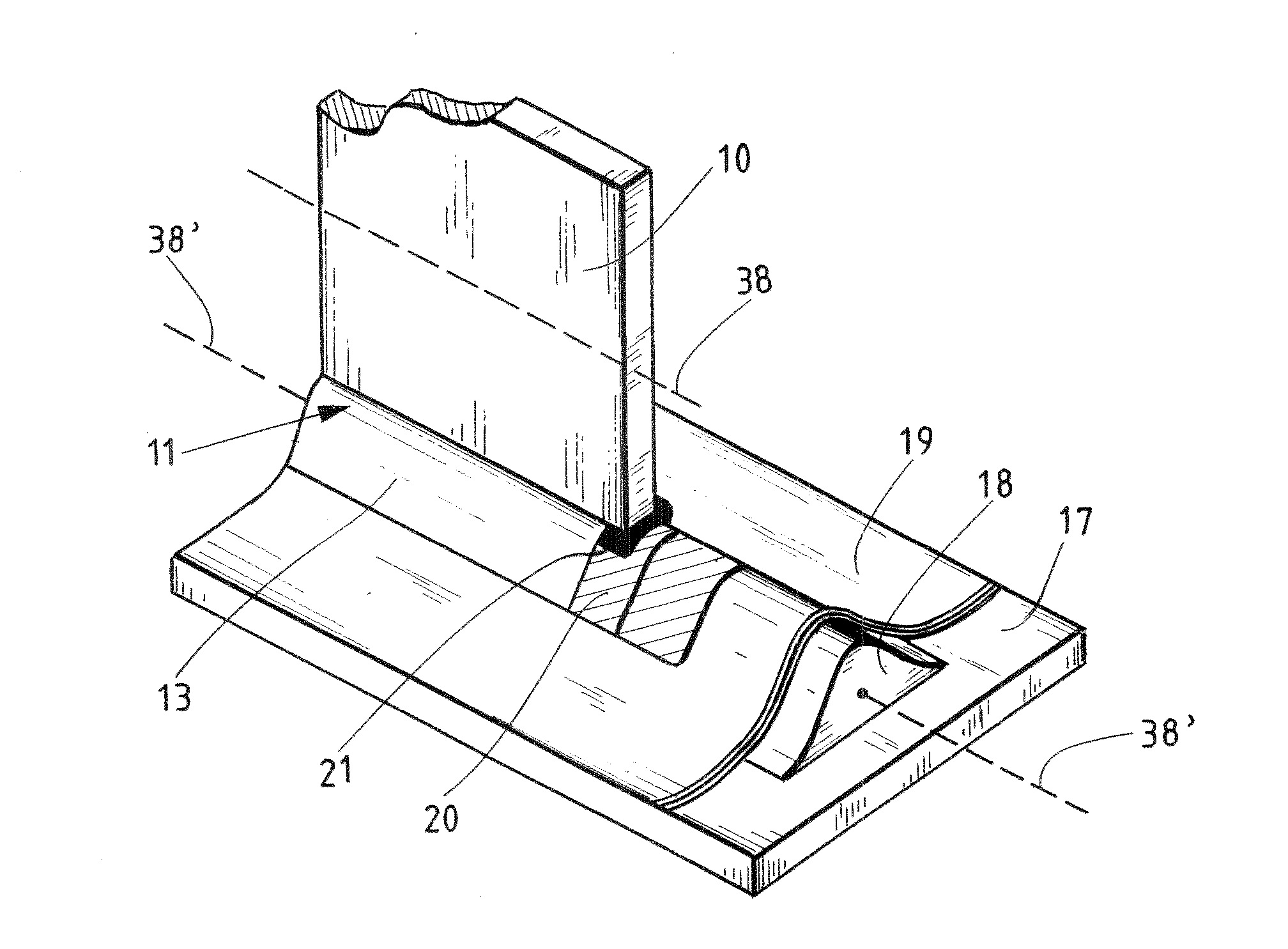
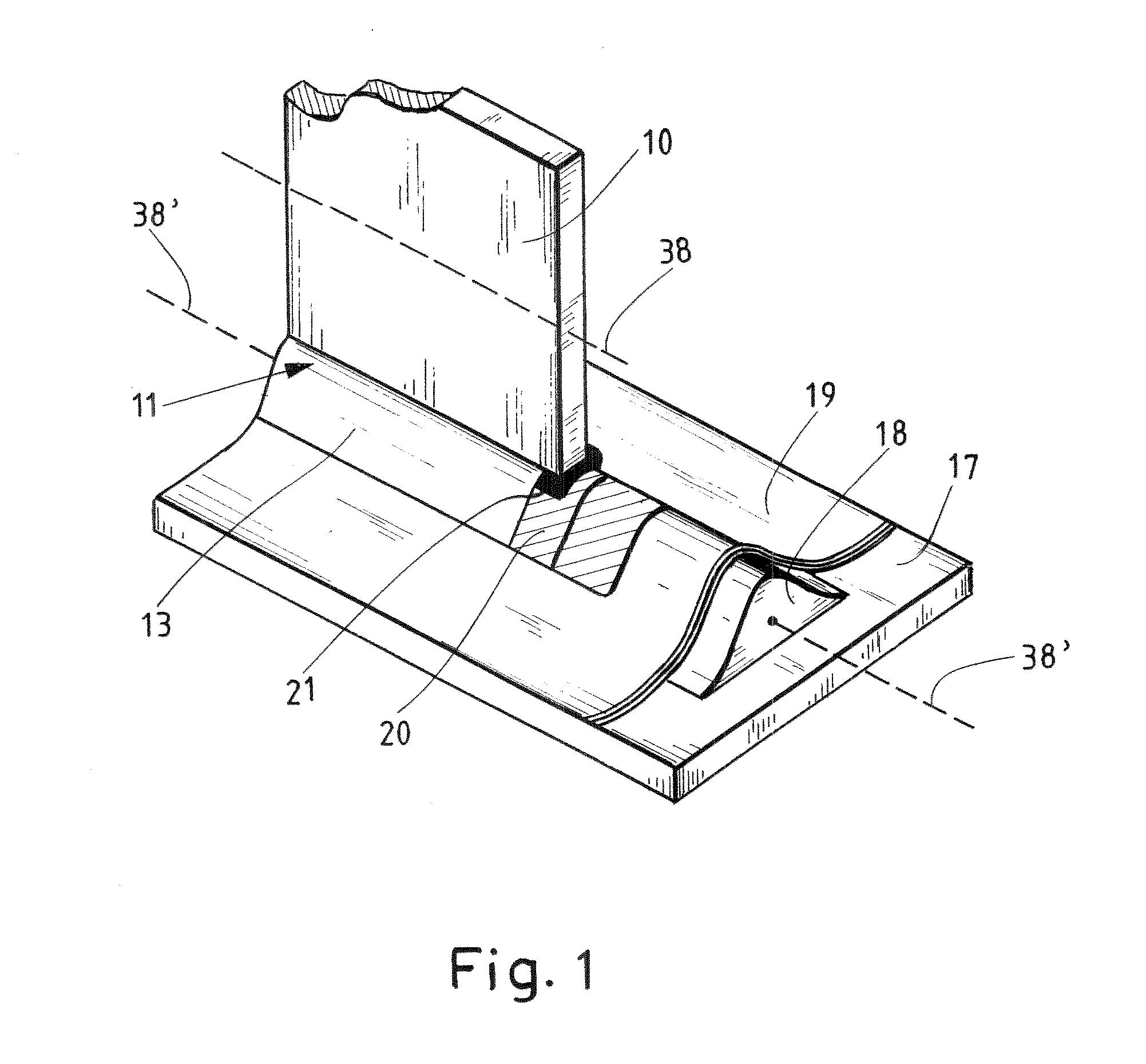
[0029]FIG. 1 shows a schematic three-dimensional representation of a shear web connection according to the invention. A supporting body 18, for example made of balsa wood or glass-fiber-reinforced plastic, is applied to a belt 17. A hardened plastic foam can also be used instead of this material. The supporting body 18 can also be produced integrally with the belt and can be made of the same material as the belt. However, in this exemplary embodiment, the supporting body 18 is adhered to the belt 17. The supporting body 18 has a longitudinal extension 38′, which is essentially parallel to the longitudinal axis of the rotor blade or respectively, under certain circumstances, can also be warped, bent and / or flexed like the belt and the rotor blade. The corresponding shape of t...


PUM

PropertyMeasurementUnit
densityaaaaaaaaaa
angleaaaaaaaaaa
angleaaaaaaaaaa

Abstract

A shear web (10, 10′) with two shear web feet (11, 11′, 12, 12′) for the connection of a pressure side (35) with a suction side (36) of a wing (37), wherein the shear web (10, 10′) has a longitudinal extension (38), which is transverse to the extension of the shear web from the suction side (36) to the pressure side (35). Also, a corresponding wing (37) and a method for the production of a wing (37). The shear web wherein at least one shear web foot (11, 11′, 12, 12′) has two connection sides (13-16′) arranged on opposite sides of the shear web (10, 10′) transverse to the longitudinal extension (38). The wing (37) has a shear web (10, 10′) and a supporting body (18-18″), which is connected with a shear web foot.

Description

BACKGROUND OF THE INVENTION[0001]The invention relates to a shear web with two shear web feet, wherein the shear web is provided for the connection of a pressure side with a suction side of a wing, wherein the shear web has a longitudinal extension, which is transverse to the extension of the shear web from the suction side to the pressure side. Furthermore, the invention relates to a wing with a corresponding shear web. Furthermore, the invention relates to the use of a supporting body for a wing for the connection of the suction side and the pressure side with a shear web as well as a method for the production of a wing.[0002]Within the framework of this application, the term wing comprises a bearing surface of an airplane, a propeller of a helicopter and in particular a rotor blade of wind power plant. If a rotor blade is discussed in the following in particular in connection with the figure description, a bearing surface of an airplane or a propeller of a helicopter shall also b...

Claims


Application Information

Patent Timeline
Patent Type & Authority Applications(United States)
IPC IPC(8): F16B11/00B32B37/02F01D5/14
CPCB64C3/185F03D1/0683Y10T403/47Y02E10/721Y10T156/10F05B2250/711Y02E10/72Y02P70/50F03D1/0675
Inventor FLACH, CHRISTIAN
Owner REPOWER SYST AG
Why Eureka
Try Eureka