Method and Apparatus for Muting Signaling in a Wireless Communication Network

a wireless communication network and signaling technology, applied in the direction of wireless communication, transmission path sub-channel allocation, instruments, etc., can solve the problems of increasing the processing resources and the time needed for prs measurement, gps or a-gps receivers may not necessarily be available in all wireless terminals, and the failure rate of gps is known to be high in indoor environments and urban canyons

Inactive Publication Date: 2011-09-22
TELEFON AB LM ERICSSON (PUBL)
View PDF14 Cites 92 Cited by
  • Summary
  • Abstract
  • Description
  • Claims
  • Application Information

AI Technical Summary

Benefits of technology

In one aspect, the present invention provides a simple method of signaling reference signal muting information to receiving radio equipment, such as UEs. (The reference signals may be, e.g., PRSs and/or CRSs.) In one or more embodiments, the present invention proposes a general solution whereby the receiving radio equipment is informed not

Problems solved by technology

GPS or A-GPS receivers, however, may not necessarily be available in all wireless terminals.
Furthermore, GPS is known to have a high failure incidence in indoor environments and urban canyons.
That, of course, increases the processing resources and the time needed for making PRS measurements, and tends to lower the accuracy of the results.
However, to date, the 3GPP standards do not specify how muting is to be implemented, nor do they specify signaling for communicating muting information to UEs or other receiving equipment that might be making use of the PRSs being transmitted by a given cell or a given cluster of neighboring cells.
While this approach offers certain advantages in terms of simplicity on the network side, it leaves receiving radio equipment with the same burdensome processing tasks, as said equipment ha

Method used


Image

  • Method and Apparatus for Muting Signaling in a Wireless Communication Network
  • Method and Apparatus for Muting Signaling in a Wireless Communication Network
  • Method and Apparatus for Muting Signaling in a Wireless Communication Network

Examples


Embodiment Construction

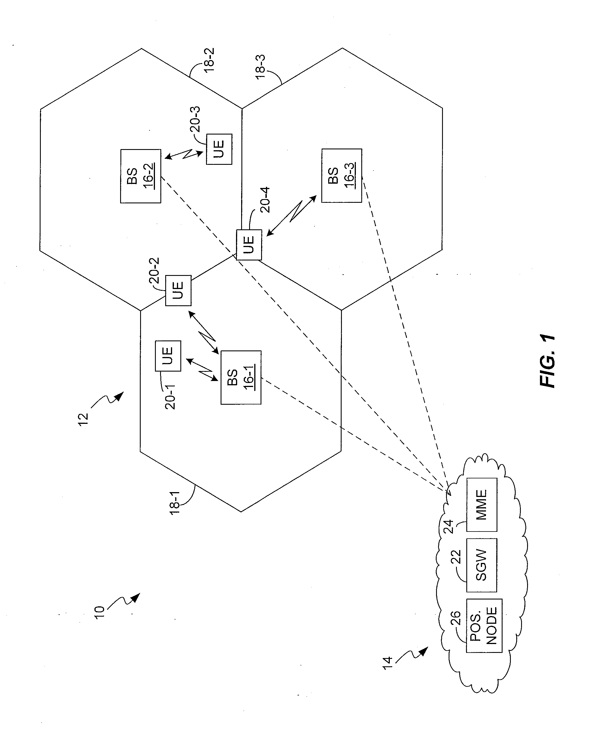
As a non-limiting example, FIG. 1 illustrates one embodiment of a wireless communication network 10, which includes a Radio Access Network (RAN) 12 and an associated Core Network (CN) 14. The RAN 12 includes a number of base stations 16, e.g., BS 16-1, 16-2, and so on. Unless needed for clarity, the reference number 16 is used to refer to BSs 16 in both singular and plural senses. Each BS 16 provides one or more “cells”18, e.g., cell 18-1 corresponding to BS 16-1, cell 18-2 corresponding to BS 16-2, and so on. The cells 18 represent the radio service coverage provided by each BS 16, for supporting communications with user equipment 20, e.g., UE 20-1, UE 20-2, and so on.

Correspondingly, the CN 14 communicatively links the UEs 20 to each other and / or to communications equipment in other networks, such as the Internet, the PSTN, etc. To that end, the CN 14 includes a number of nodes or other functional entities. By way of simplified example, the illustrated CN 14 is depicted as includi...


PUM


Abstract

In one aspect, the present invention provides a simple method of signaling reference signal muting information to receiving radio equipment, such as items of user equipment (UEs). The reference signals may be positioning reference signals and/or cell-specific reference signals, for example. In one or more embodiments, the present invention proposes a general solution whereby the receiving radio equipment is informed not only on whether muting is used in general in a cell, but also the particular timing and formatting of such muting. Further, the contemplated method provides for the use of dynamic muting patterns, and thus avoids the need for statically defined muting patterns, and provides for coordinated muting control, across two or more network cells. In at least one embodiment, static or less dynamic aspects of the muting configuration is signaled via higher-layer signaling, while lower-layer signaling is used to signal more dynamic aspects of the muting configuration.

Description

FIELD OF THE INVENTIONThe present invention generally relates to interference management in wireless communications networks, and particularly relates to controlling the muting of reference signals transmitted by one or more base stations in the network and signaling related muting configuration information.BACKGROUNDWireless communication networks use reference signal transmissions to support a variety of key functions. In this regard, a “reference” signal provides receiving radio equipment with some type of reference information—timing, frequency, phase, etc.—that enables certain measurements by the receiving equipment. For example, cell-specific reference signals, also referred to as common reference signals or CRSs provide receiving radio equipment with a basis for estimating propagation channel conditions. Other physical-layer reference signals include so called positioning reference signals or PRSs, which are particularly contemplated for newer, more capable networks, such as ...

Claims


Application Information

Patent Timeline
IPC IPC(8): H04B7/00
CPCH04L5/0044H04L5/0048G01S1/042H04W64/00G01S1/20H04L5/0091H04W74/002
Inventor SIOMINA, IANAKAZMI, MUHAMMAD ALI
Owner TELEFON AB LM ERICSSON (PUBL)
Why Eureka
Try Eureka