
Carpal active protection systems (CAPS)

a protection system and carpal technology, applied in the field of carpal active protection systems, can solve the problems of not delivering any form of pressure to the distal forearm, and achieve the effects of enhancing venous sufficiency, enhancing arterial blood inflow, and enhancing venous outflow

Inactive Publication Date: 2011-09-22
ORON AMIR
View PDF0 Cites 6 Cited by
  • Summary
  • Abstract
  • Description
  • Claims
  • Application Information

AI Technical Summary

Benefits of technology

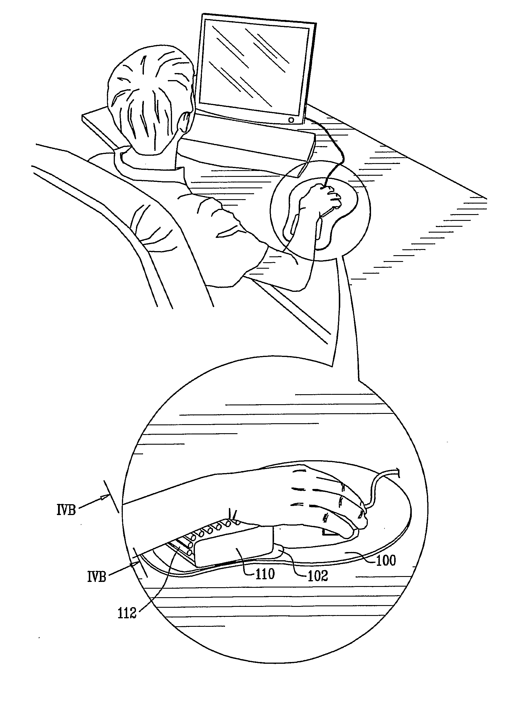
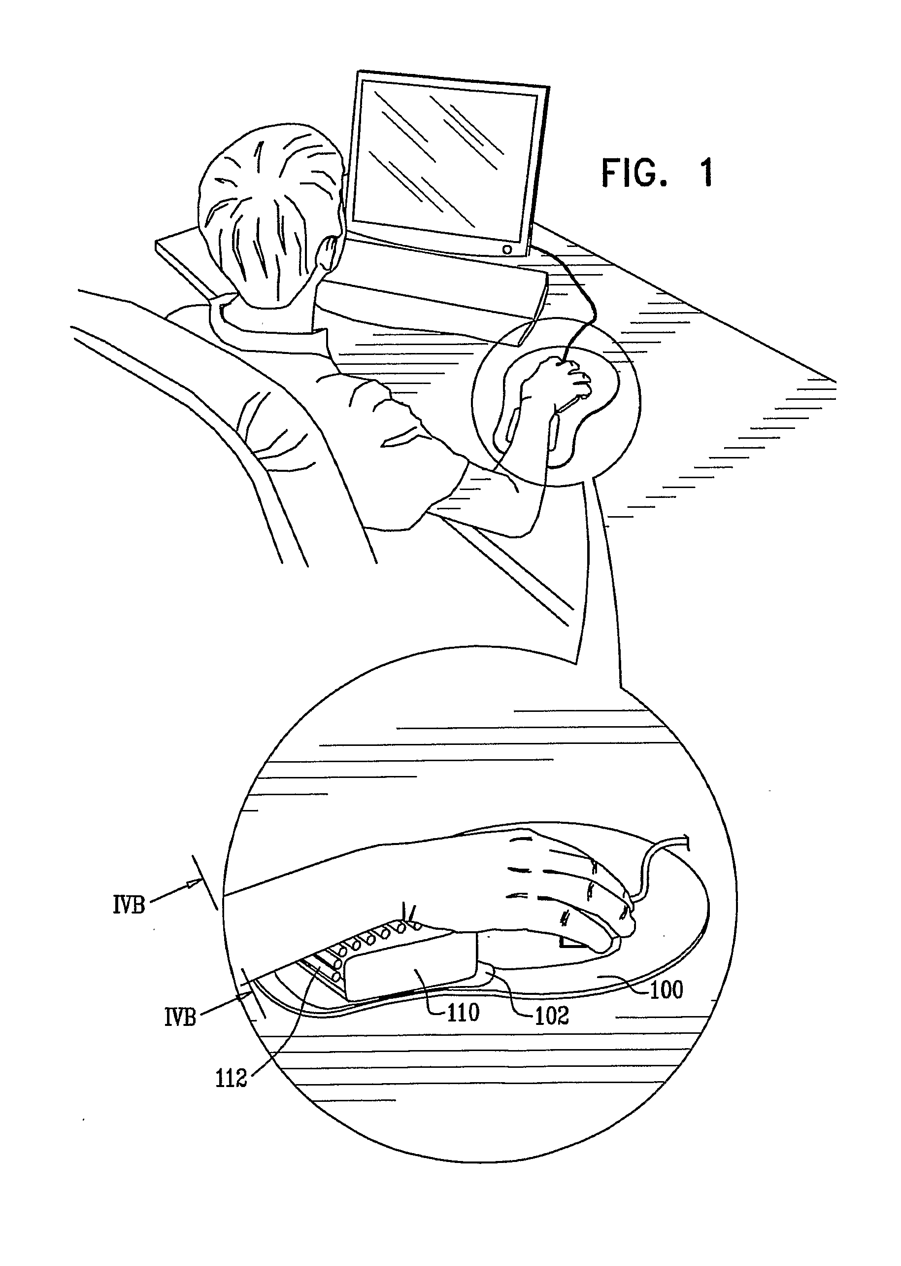
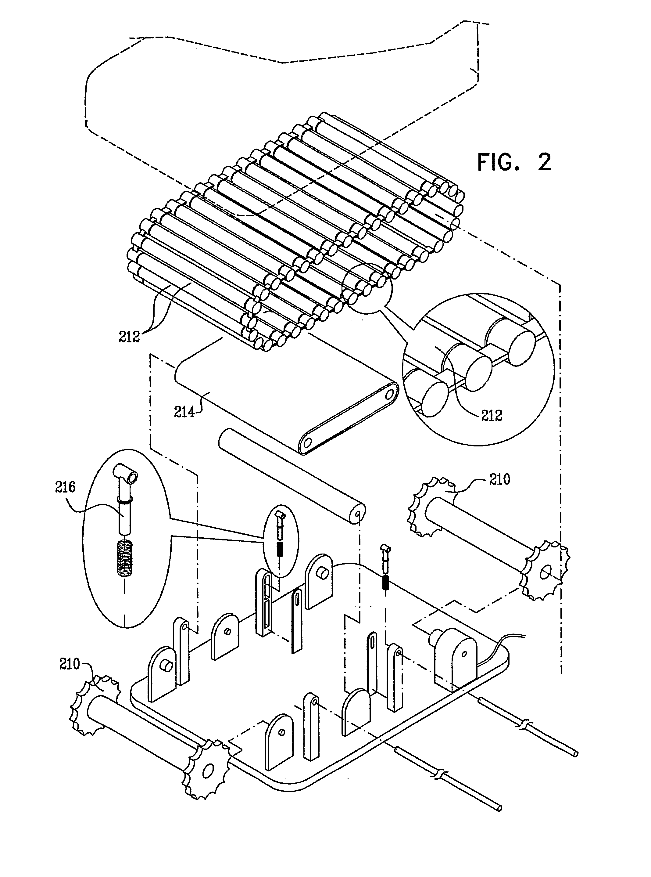
A specially designed support is disclosed aimed at supporting the proximal and / or distal forearm and wrist areas while actively transferring a limited and directed pressure to the volar aspect of the distal forearm and wrist. The action is not coupled to movement performed by the user. The ergonomically designed support comes into contact with both wrist area and distal forearm and may also have a designed support supporting the proximal forearm and elbow region while distance between the two supports may be adjusted. The support exerts a predetermined pressure wave which causes an enhancement in venous outflow which in turn causes enhanced arterial blood inflow to the carpal area which is to effect a circulation modifying action in the wrist and distal forearm area. The pressure directed at the volar aspect of the distal forearm acts in a direction from distal to proximal at a determined magnitude and cycle repetition rate thus enhancing venous sufficiency. This force, by enhancing venous return from the area, acts to prevent ailments caused by use of computer input devices (e.g. computer mouse) in general and specifically carpal tunnel syndrome. The support further comprises a motor exerting said repetitive pressure or possibly other means for forming such movement as hereby described. The support utilizes continuous movement to alter and better the physiology of computer users, lessening chances of occurrence of pathology specifically known as carpal tunnel syndrome and possibly alleviating this condition altogether. The support may further be incorporated as a support built at a width similar to a keyboard or as two prefabricated supports for each of the hands.
Accordingly, it is a principle object of the invention to provide a support to a computer users' forearm which will be placed on the work surface (presumably a desk) and exert a force directed in a distal to proximal direction, at determined magnitude, location and cycle rate to cause enhancement of venous return and thus circulation within the vicinity of the Carpal Tunnel.
It is further another object of the invention that said support may tend to exert said predetermined force to an area presumably containing major venous structures and may as well exert this pressure wave to a length beyond venous valves situated within the veins of the forearm, thus preventing return of venous blood past these valves.
It is further another object of the invention that the proximal support may be stationed on a set of railings or other means which may be adjustable to allow for a change in work angle and may allow support to the proximal forearm when the actual support of the proximal part is not situated on the computer users' desk but i.e. is situated in mid air. It is pointed out that this mid air position may make use of a “spring” mechanism thus allowing a “bouncing” effect to said rest.
It is further another object of the invention to utilize a “target” like pattern i.e. incorporating a graphic design “aiming” or “pointing” the user to placing the hand in the desired spot in as short an interval and as correct as possible—thus shortening “parking” times.
It is further another object of the invention to allow incorporation of possible embodiments of it to be incorporated or used in conjunction with a laptop or portable computer—allowing for incorporation of the above objects as well as extending the wrist resting area which is another object of the invention.

Problems solved by technology

However, the wrist support disclosed in this application does not deliver any form of pressure to the distal forearm.
However, the disclosed in this patent relates to a vibrating massage with no determined direction and covering only the wrist area as does a conventional mouse or keyboard pad.

Method used


Image

  • Carpal active protection systems (CAPS)
  • Carpal active protection systems (CAPS)
  • Carpal active protection systems (CAPS)

Examples


Embodiment Construction

FIG. 4B depicts the superficial venous system of the distal forearm and wrist which is tied to and on which the present invention relies upon and relates to. It should be stated that processes causing pressure within the carpal tunnel may alter blood supply to the median nerve causing carpal tunnel syndrome and / or neurotrophic changes over time. It should be stated that tenosynovitis as a pathological process may bring about enhancement of structures within the carpal tunnel thus impinging on blood supply and / or may be a pathological process in its own right, causing pain and discomfort. Since FIG. 4B depicts the venous blood supply of the distal forearm. The current invention utilizes the placement of force relaying modules within the vicinity of these venous structures to enhance blood flow along them in a distal to proximal direction. It is further stated that force acting within the vicinity of these structures may cause their collapse thus rendering them almost free of blood fr...


PUM


Abstract

A specially designed support is disclosed aimed at supporting the proximal and / or distal forearm and wrist areas while actively transferring a limited and directed pressure to the volar aspect of the distal forearm and wrist. The action is not coupled to movement performed by the user. This force, in turn, allows for enhancing venous return from the area, and thus acts to prevent ailments caused by use of computer input devices (e.g. computer mouse, keyboard). The support further comprises a motor exerting said repetitive pressure or possibly other means for forming such movement as described. The support utilizes continuous movement to alter and better the physiology of computer users, lessening chances of occurrence of pathology specifically known as carpal tunnel syndrome and possibly alleviating this condition altogether The support may be used in a mouse pad, keyboard rest or arm rest. This design may be augmented by other modifications and additions which may be utilized in conjunction with the current invention or as inventions or modifications in their own right.

Description

REFERENCES CITEDU.S. Patent DocumentsU.S. Pat. No. 5,490,647 issued Feb. 13, 1996 to Gregory H. RiceU.S. Pat. No. 5,566,913 issued Oct. 22, 1996 to David M. ProkopU.S. Pat. No. 5,375,800 issued Dec. 27, 1994 to Katherine C. Wilcox et. al.U.S. Pat. No. 5,120,117 issued Jun. 9, 1992, to Chauncey L. WilliamsU.S. Pat. No. 5,628,483 issued May 13, 1997 to Mark R. Smith and Philip G. WessellsU.S. Pat. Application No. 2002 / 0113175 A1 filed Feb. 12, 2002 by Carmen DillonU.S. Pat. No. 6,599,259 B2 issued Jul. 29, 2003 to Brett J. MuirU.S. Pat. No. 6,323,841 B1 issued on Nov. 27, 2001 to Sun-Long LaiU.S. Pat. Application No. 2004 / 0189606 A1 published Sep. 30, 2004 by Eakkapong PowpongU.S. Pat. No. 6,679,857 B1 issued Jan. 20, 2004 to Bastia et. al.U.S. Pat. Application Publication No. 2004 / 0089771 A1 published May 13, 2004 by Zsolt PapU.S. Pat. No. 5,674,423 issued Oct. 7, 1997 to Dennis E. Wright Sr.U.S. Pat. No. 5,596,481 issued Jan. 21, 1997 to Peter M. Liu, Robert L. McMahanU.S. Pat. No. ...

Claims


Application Information

Patent Timeline
IPC IPC(8): A61H15/00
CPCA61H7/004A61H2205/065A61H15/0078
Inventor ORON, AMIR
Owner ORON AMIR
Learn More