Information processing apparatus, image forming apparatus, and information processing program

a technology of image forming apparatus which is applied in the field of information processing apparatus, image forming apparatus, and information processing program, can solve the problems of difficult connection of measuring instruments, difficult to analyze the contents accessed by the cpu, and difficult to use observation results

Inactive Publication Date: 2011-09-22
RICOH KK
View PDF17 Cites 13 Cited by
  • Summary
  • Abstract
  • Description
  • Claims
  • Application Information

AI Technical Summary

Benefits of technology

[0009]It is an object of the present invention to at lea...

Problems solved by technology

However, by this method, finding the location of the cause of the error using the observation result has been an extremely difficult task.
Furthermore, in an information processing apparatus with a built-in CPU, it has been difficult to connect a measuring instrument to the CPU I/F, further making it difficult to analyze the contents accessed by the CPU.
However, once an e...

Method used


Image

  • Information processing apparatus, image forming apparatus, and information processing program
  • Information processing apparatus, image forming apparatus, and information processing program
  • Information processing apparatus, image forming apparatus, and information processing program

Examples


first embodiment

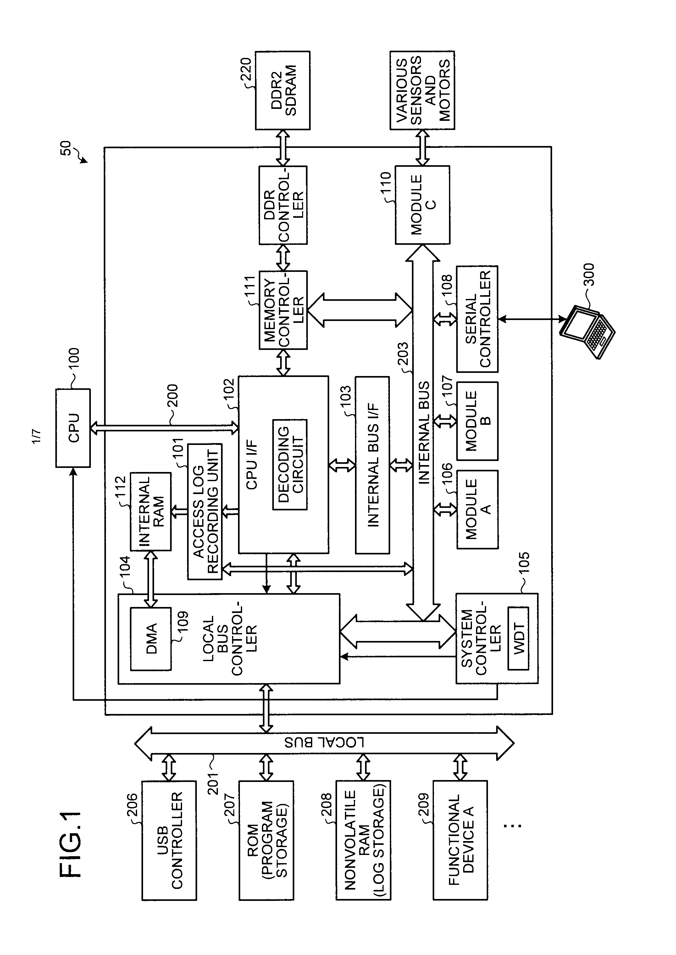
[0021]A hardware configuration of an information processing apparatus will now be explained with reference to FIG. 1. An information processing apparatus 50 according to a first embodiment of the present invention includes a central processing unit (CPU) 100, an access log recording unit 101, a CPU interface (I / F) 102, an internal bus I / F 103, a local bus controller 104, a system controller 105, a module A 106, a module B 107, a serial controller 108, a module C 110, a memory controller 111, an internal random access memory (RAM) 112, a double data rate 2 synchronous dynamic random access memory (DDR2 SDRAM) 220, a universal serial bus (USB) controller 206, a read-only memory (ROM) 207, a nonvolatile RAM 208, and a functional device A 209. The CPU 100 and the CPU I / F 102 are connected via a CPU bus 200. The CPU I / F 102, the access log recording unit 101, the internal bus I / F 103, the local bus controller 104, and the memory controller 111 are connected via a bus (not illustrated). T...

second embodiment

[0033]A second embodiment of the information processing apparatus, the image forming apparatus, and the information processing program will now be explained. The portions that are the same as those in the first embodiment will be given the same reference numerals, and explanations thereof will be omitted hereunder.

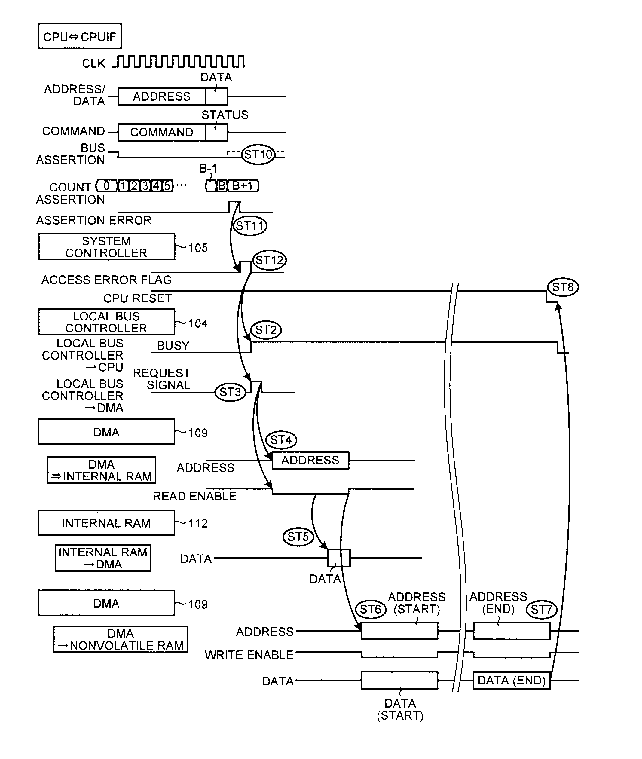
[0034]In the first embodiment, any occurrence of an error in the CPU 100 is detected by the function of the WDT. However, in the second embodiment, occurrence of an error is detected by detecting the status of the CPU bus 200. FIG. 6 is a schematic view illustrating an exemplary hardware configuration of the information processing apparatus 50 according to the second embodiment. The configuration according to the second embodiment is different from that according to the first embodiment in that the CPU I / F 102 includes an access timing counter. The access timing counter counts time elapsed since the CPU bus 200 was asserted by the CPU 100 to transmit signals to the target ...


PUM


Abstract

A CPU I/F decodes a signal transmitted from a CPU to a target location, and transmits the decoded signal to a mediating module mediating with the target location and to an access log recording unit. The access log recording unit generates an access log using the signal received from the CPU I/F, and stores the access log in an internal RAM. A DMA stores the access log stored in the internal RAM in a nonvolatile RAM when a system controller detects any occurrence of an error in the CPU.

Description

CROSS-REFERENCE TO RELATED APPLICATIONS[0001]The present application claims priority to and incorporates by reference the entire contents of Japanese Patent Application No. 2010-063273 filed in Japan on Mar. 18, 2010.BACKGROUND OF THE INVENTION[0002]1. Field of the Invention[0003]The present invention relates to an information processing apparatus, an image forming apparatus, and an information processing program.[0004]2. Description of the Related Art[0005]Conventionally, some information processing apparatuses have a central processing unit (CPU) interface (I / F) that mediates communications in a CPU. Some of such information processing apparatuses have capabilities of analyzing, when an error occurs, contents accessed by the CPU, and finding the location causing the error. For example, by a known method, a measuring instrument is connected to the CPU I / F to observe the CPU I / F, and when an error occurs, a result of the observation is used in analyzing contents accessed by the CPU ...

Claims


Application Information

Patent Timeline
IPC IPC(8): G06F11/07
CPCG06F11/0757G06F11/0781G06F11/0778G06F11/0733
Inventor HIRATA, SATOSHI
Owner RICOH KK
Why Eureka
Try Eureka