Media application

Inactive Publication Date: 2011-09-29
KODAK CANADA ULC
View PDF4 Cites 0 Cited by
  • Summary
  • Abstract
  • Description
  • Claims
  • Application Information

AI Technical Summary

Benefits of technology

[0015]An apparatus is provided, in one embodiment, for applying media to a cylindrical roller. The cylindrical roller has a cylindrical surface which could be a partial or complete cylinder. The roller is adapted to wrap the donor media on it. A carriage is movably mounted on a support and is operable for conveying the roller along a path. A controller, which could include a plurality of controllers, causes the roller to rotate to wrap a first portion of the donor element onto the cylindrical surface while applying tension to the donor element to establish a region of contact between the first portion of the donor element and the cylindrical surface. The controller or controllers cause the roller to rotate while decreasing the applied tension to alter the region of contact between the first portion of the donor element and the cylindrical surface. The controller or controllers then cause the roller to rotate to wrap an additional portion of the donor element onto the cylindrical surface after the region of contact between the first portion of the donor element and the cylindrical surface has been altered. The carriage is then caused to operate to move the roller along the path while transferring the first portion of the donor element and the additional portion of the donor element from the cylindrical surface to a substrate.

Problems solved by technology

For example, mis-alignment between the media roll and the roller can lead to a non-uniform web tension which can cause wrinkles to form during loading.
The difficulties associated with the loading operation can be further compounded when media is loaded from a plurality of media rolls (e.g. different colored donor elements) and each of the media rolls has a different orientation with respect to the roller sufficient to alter the web tension between the different loadings.
Entrapped bubbles, wrinkles and the like can cause variances in the amount of donor material that is transferred to substrate 10 which can lead to various undesired image artifacts.

Method used


Image

  • Media application
  • Media application
  • Media application

Examples


Embodiment Construction

[0025]Throughout the following description, specific details are set forth in order to provide a more thorough understanding of the invention. However, the invention may be practiced without these particulars. In other instances, well known elements have not been shown or described in detail to avoid unnecessarily obscuring the disclosure. Accordingly, the specification and drawings are to be regarded as illustrative rather than restrictive. It is to be further noted that the drawings are not to scale.

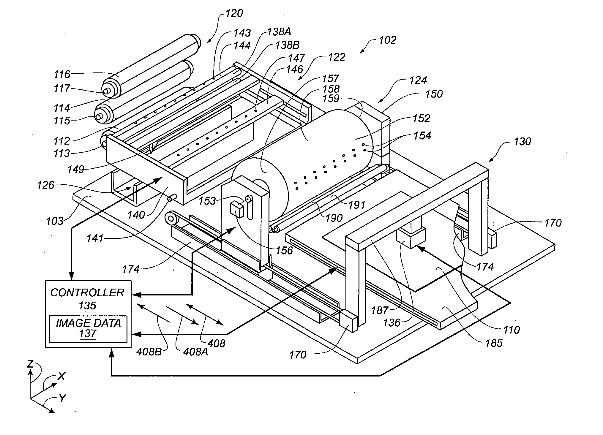
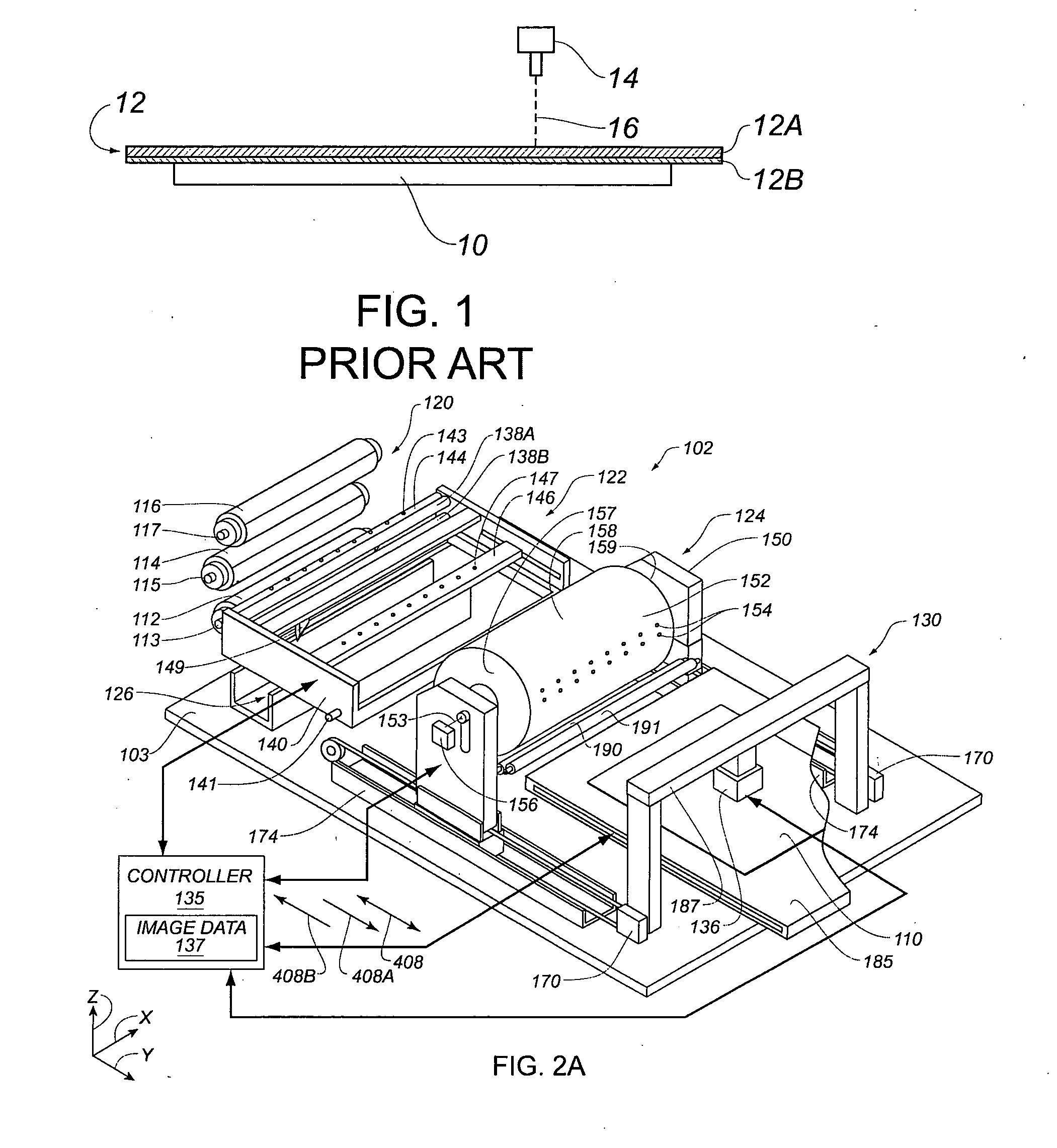
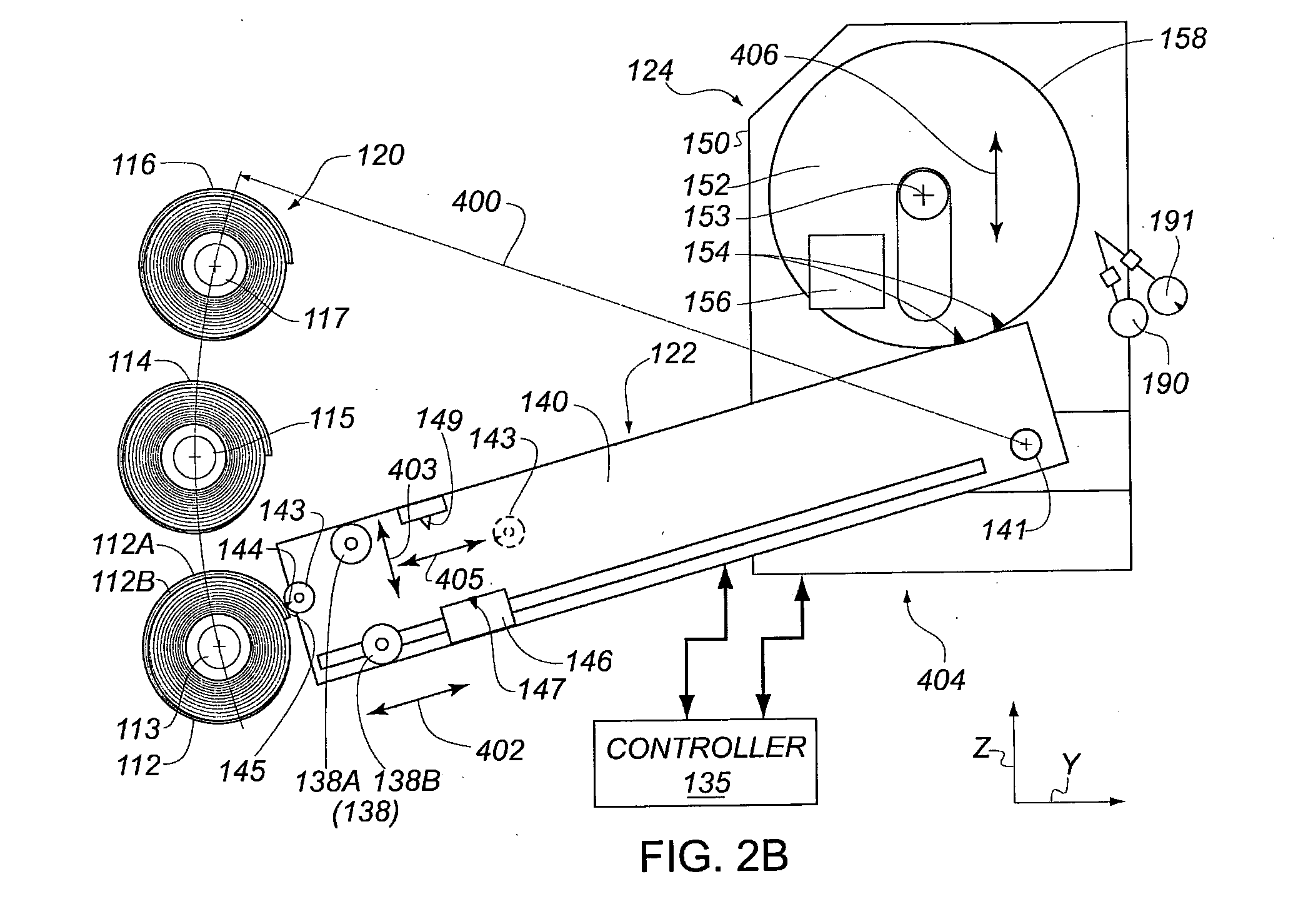
[0026]FIGS. 2A, 2B, 2C, 2D, 2E, 2F, 2G, 2H, 2I, 2J, 2K, 2L, 2M and 2N schematically depict various parts of apparatus 102 and methods of operation thereof according to an example embodiment of the invention. In this example embodiment of the invention, various thermal transfer donor elements 112, 114 and 116 are assembled on respective media rolls 113, 115 and 117. Each of the donor elements 112, 114 and 116 includes a support layer and a transfer layer. In this illustrated embodiment,...


PUM

PropertyMeasurementUnit
Thicknessaaaaaaaaaa
Thicknessaaaaaaaaaa
Thicknessaaaaaaaaaa

Abstract

A method and apparatus are provided which include providing a rotatable roller with a cylindrical surface adapted to wrap the donor element on the surface. A donor element is secured to the roller and a first portion of the donor element is wrapped onto the cylindrical surface while applying tension to the media. The tension is then decreased to alter a region of contact between the first portion of the donor element and the cylindrical surface. An additional portion of the donor element is then wrapped onto the cylindrical surface. The donor element is then transferred from the roller to a substrate.

Description

FIELD OF THE INVENTION[0001]This invention relates to methods and apparatus for applying media to a cylindrical roller. The cylindrical roller can be adapted to convey the media along a conveying path. A cylindrical roller assembly in accordance with the present invention is especially useful in imaging systems, particularly when media incorporating donor material are exposed to transfer donor material onto a surface, and after exposure, are removed from the surface.BACKGROUND OF THE INVENTION[0002]Color flat panel displays, such as liquid crystal displays and the like, typically incorporate color filters used to provide pixels with color. One technique for fabricating color filters involves a laser-induced thermal transfer process. A particular prior art thermal transfer process is illustrated schematically in FIG. 1. A substrate 10, known in the art as a receiver element, is overlaid with a donor element 12, known in the art as a donor sheet. Donor element 12 typically incorporate...

Claims


Application Information

Patent Timeline
IPC IPC(8): B32B38/18B32B37/30
CPCB41J2/475B41J17/24G02F1/133516B41M2205/06B41M5/38221
Inventor RARAMA, JEREMIASZAVOROTNY, YURIMONTGOMERY, DARCY T.
Owner KODAK CANADA ULC
Why Eureka
Try Eureka