
Air cleaner device

a cleaner and air technology, applied in the direction of machines/engines, combustion-air/fuel-air treatment, separation processes, etc., to achieve the effect of enhancing filtration efficiency, facilitating smooth passage of intake air, and facilitating passag

Inactive Publication Date: 2011-09-29
HONDA MOTOR CO LTD
View PDF15 Cites 48 Cited by
  • Summary
  • Abstract
  • Description
  • Claims
  • Application Information

AI Technical Summary

Benefits of technology

[0006]Embodiments or the present invention have been made in view of the foregoing situations and it is an object of the present invention to provide an air cleaner device that can ensure a good intake air stream and that can be built compactly.

Problems solved by technology

This, however, restricts arrangements of parts in the longitudinal direction of the air cleaner device, which could lead to a longitudinally long air cleaner device in a vehicle.

Method used


Image

  • Air cleaner device
  • Air cleaner device
  • Air cleaner device

Examples


Embodiment Construction

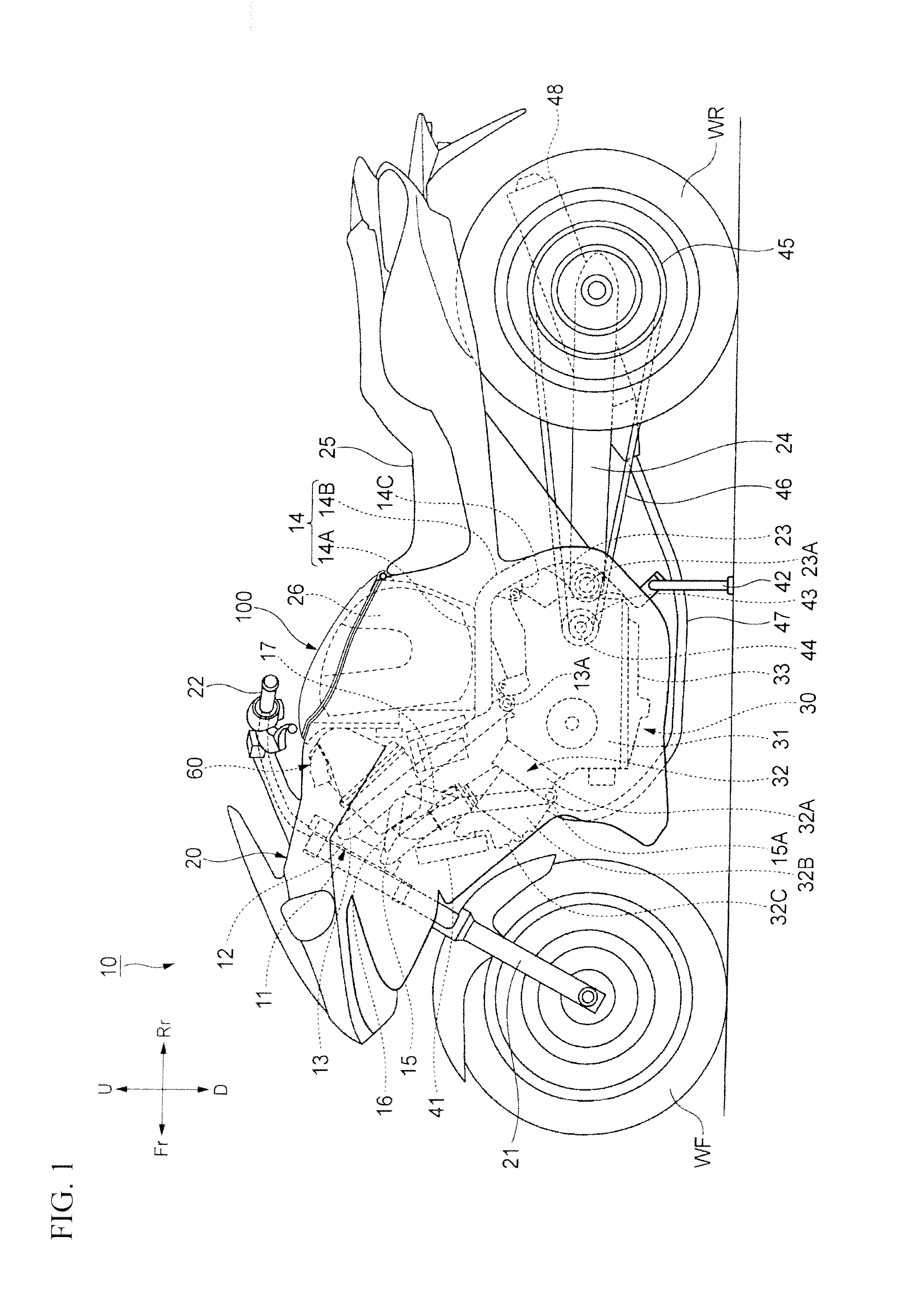
[0030]Embodiments of an air cleaner device to which the present invention is applied will be described in detail below with reference to the accompanying drawings. The drawings should be viewed in the direction of reference symbols. Throughout the descriptions given hereunder, expressions indicating directions including front and rear, right and left, and upper and lower mean the same directions as those as viewed from a rider. In the drawings, an arrow Fr indicates forward of the vehicle, an arrow Rr indicates rearward of the vehicle, an arrow L indicates leftward of the vehicle, an arrow R indicates rightward of the vehicle, an arrow U indicates upward of the vehicle, and an arrow D indicates downward of the vehicle.

[0031]Referring to FIG. 1, a vehicle such as motorcycle 10 can include a vehicle body frame 11 which is covered in a vehicle body cover or fairing 20 made, for example, of a synthetic resin.

[0032]The vehicle body frame 11 can include a head pipe 12, a pair of left and ...


PUM

PropertyMeasurementUnit
Widthaaaaaaaaaa

Abstract

An air cleaner device can include an air cleaner case including a case main unit and a cover. An intake duct can be disposed on the cover, and an intake path can be disposed on the case main unit. An air cleaner element can be accommodated in the air cleaner case. When the air cleaner device is mounted in a vehicle and viewed from a vehicle side, the air cleaner case is formed to be vertically long. The intake duct is formed to have an upstream-side opening portion thereof oriented toward a first side of the air cleaner case, and a downstream-side opening portion thereof can be oriented downwardly. The intake path is formed to have an upstream-side opening portion thereof oriented upwardly to face the downstream-side opening portion of the intake duct, and a downstream-side opening portion thereof is oriented toward a second side of the air cleaner case.

Description

BACKGROUND[0001]1. Field[0002]The present invention relates to an air cleaner device.[0003]2. Description of the Related Art[0004]A known air cleaner device includes an air cleaner element disposed between a dirty room and a clean room, and an intake duct and an intake path disposed to extend vertically in parallel with each other, the intake duct having a downstream-side opening portion facing a rearward direction and the intake path having an upstream-side opening portion facing the same rearward direction as the downstream-side opening portion of the intake duct. Such a configuration is shown, for example, in Japanese Patent Laid-Open No. 2003-247468 (Patent Document 1).[0005]In the air cleaner device disclosed in Patent Document 1, the downstream-side opening portion of the intake duct and the upstream-side opening portion of the intake path face the same direction. This results in an intake air stream being substantially U-shaped, which can restrict the intake air stream as com...

Claims


Application Information

Patent Timeline
IPC IPC(8): B60K13/02B01D46/00
CPCB01D46/0005B01D46/0041B01D46/10B01D2279/60F02M35/162F02M35/02416F02M35/02491F02M35/10039F02M35/0203
Inventor ABE, RYUICHISHOMURA, TAKAAKIKOBAYASHI, KOKI
Owner HONDA MOTOR CO LTD
Features
  • Generate Ideas
  • Intellectual Property
  • Life Sciences
  • Materials
  • Tech Scout
  • Unparalleled Data Quality
  • Higher Quality Content
  • 60% Fewer Hallucinations
Learn More