Valve characteristic controlling apparatus and method for internal combustion engine

a technology of characteristic controller and internal combustion engine, which is applied in the direction of valve arrangement, combustion engine, machine/engine, etc., can solve the problems of increasing pumping loss, and achieve the effect of alleviating insufficient fuel atomization, reducing the flow rate of intake air, and reducing the flow ra

Active Publication Date: 2006-05-04
TOYOTA JIDOSHA KK
View PDF2 Cites 14 Cited by
  • Summary
  • Abstract
  • Description
  • Claims
  • Application Information

AI Technical Summary

Benefits of technology

[0016] When the center of the operating angle of the intake valve is retarded, the opening timing of the intake valve is also retarded accordingly. As a result, a piston is located farther away from the exhaust top dead center at the time the intake valve is opened (that is, at the opening timing of the intake valve). Therefore, when the intake valve is opened, the combustion chamber has a lower pressure and the air is introduced into the combustion chamber at a higher flow rate. Such a higher flow rate of the intake air supplements insufficient fuel atomization in the combustion chamber. In other words, the higher flow rate of the intake air alleviates the insufficient fuel atomization.
[0017] As mentioned above, when the engine load is relatively low (lower than the predetermined value), insufficient fuel atomization is relatively more likely to occur due to a small intake air amount into the combustion chamber. Therefore, the alleviation of insufficient fuel atomization by the higher flow rate of the intake air significantly contributes to improvement in the combustion state. As a result, the fuel consumption capability is improved. The more the center of the operating angle is retarded and the larger the intake air amount is (that is, the higher the engine load is), the more the insufficient fuel atomization is alleviated and the more the fuel efficiency is improved as a result.

Problems solved by technology

When the operating angle of the intake valve is reduced and the opening timing of the intake valve (the timing the intake valve switches from the closed state to the open state) is retarded, an intake resistance (a resistance of the intake air that is introduced from an intake manifold to a combustion chamber) increases, causing an increase in pumping loss.

Method used


Image

  • Valve characteristic controlling apparatus and method for internal combustion engine
  • Valve characteristic controlling apparatus and method for internal combustion engine
  • Valve characteristic controlling apparatus and method for internal combustion engine

Examples


Embodiment Construction

[0028] Hereinafter, an embodiment of the invention will be described in detail with reference to FIGS. 1 through 6.

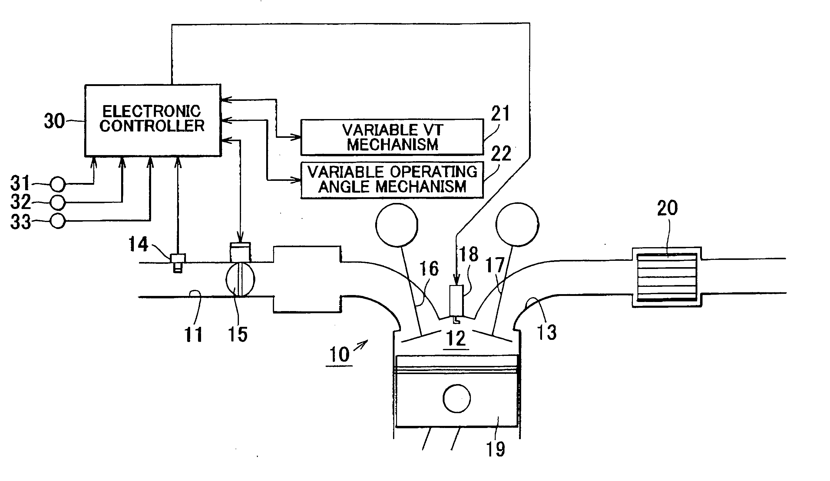
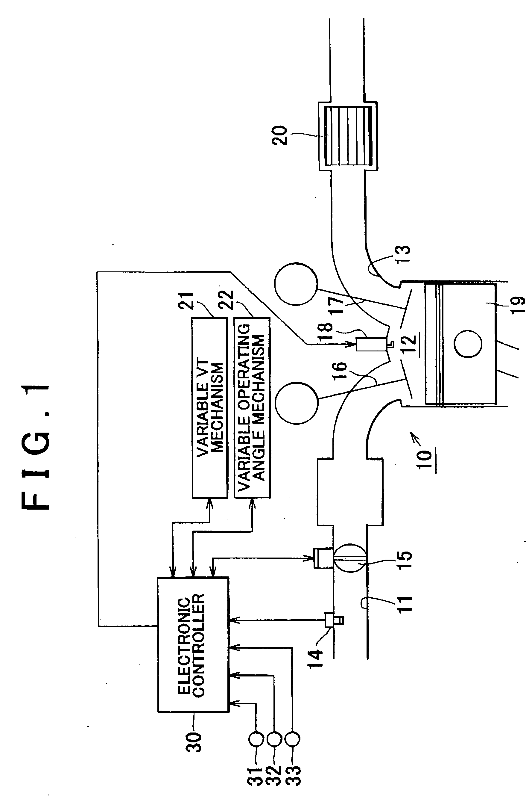
[0029]FIG. 1 schematically shows the structure of an on-board internal combustion engine 10 according to this embodiment. As shown in FIG. 1, the internal combustion engine 10 is mainly formed from an intake passage 11, a combustion chamber 12, and an exhaust passage 13.

[0030] An air flow meter 14 and a throttle valve 15 are provided in the intake passage 11 of the internal combustion engine 10. The air flow meter 14 detects an air flow rate in the intake passage 11. The throttle valve 15 changes the flow path area in the intake passage 11 to change the air flow rate. The intake passage 11 is connected to the combustion chamber 12 through an intake valve 16. The combustion chamber 12 is connected to the exhaust passage 13 through an exhaust valve 17. The intake valve 16 and the exhaust valve 17 are driven according to revolution of the internal combustion engine 10. M...


PUM


Abstract

An electronic controller variably controls the center of an operating angle of an intake valve as follows: when an engine load factor is equal to or higher than a threshold in a low load operation, the electronic controller advances the center of the operating angle with a decrease in the engine load factor. When the engine load factor is lower than the threshold in the low load operation, the electronic controller retards the center of the operating angle with a decrease in the engine load factor.

Description

INCORPORATION BY REFERENCE [0001] The disclosure of Japanese Patent Application No. 2004-317203 filed on Oct. 29, 2005 including the specification, drawings and abstract is incorporated herein by reference in its entirety. BACKGROUND OF THE INVENTION [0002] 1. Field of the Invention [0003] The invention generally relates to a valve characteristic controller that is used for an internal combustion engine having a variable valve timing mechanism and a variable valve operating angle mechanism. More particularly, the invention relates to improvement in a control for improving fuel efficiency in a low load operation. [0004] 2. Description of the Related Art [0005] Variable valve characteristic mechanisms for changing characteristics of engine valves (intake and exhaust valves) have been practically used in internal combustion engines such as on-board internal combustion engines (e.g., Japanese Laid-Open Patent Publication No. JP 2001-263015 A). Examples of the variable valve characterist...

Claims


Application Information

Patent Timeline
Patent Type & Authority Applications(United States)
IPC IPC(8): F02D13/02
CPCF02D13/0226F02D13/0238Y02T10/18Y02T10/12
Inventor YUI, TAKASI
Owner TOYOTA JIDOSHA KK
Why Eureka
Try Eureka