Fuel injection device

a fuel injection device and fuel technology, applied in the direction of fuel injection apparatus, machine/engine, charge feed system, etc., can solve the problems of difficult to improve the durability and responsibility of the valve portion of the fuel injection device, and achieve the effect of accurate shutting down the fuel communication, increasing the surface pressure of the abutting portion, and reducing the abutting area

Active Publication Date: 2011-09-29
DENSO CORP
View PDF5 Cites 10 Cited by
  • Summary
  • Abstract
  • Description
  • Claims
  • Application Information

AI Technical Summary

Benefits of technology

[0005]The inventors of the present application studied about a fuel injection device in order to accurately shut a fuel communication between the pressing surface of the pressing member and the opening wall surface. That is, the inventors of the present application studied regarding a structure for increasing the surface pressure of the abutting portion by reducing an abutting area between the pressing surface and the opening wall surface. Specifically, an outflow depressed portion and an inflow depressed portion are formed on the opening wall surface or the pressing surface, thereby reducing the abutting area between the opening wall surface and the pressing surface.
[0007]The present invention is made in view of the above matters, and it is an object of the present invention to provide a fuel injection device, which can improve the responsibility of a valve portion while improving durability in the fuel injection device.
[0009]In the fuel injection device, one of the outflow peripheral surface portion and the outflow-opposite surface portion of the opening wall surface and the pressing surface is provided with an outflow depressed portion depressed in the displacement axis direction to a side opposite to the other one of the outflow peripheral surface portion and the outflow-opposite surface portion, and one of the inflow peripheral surface portion and the inflow-opposite surface portion of the opening wall surface and the pressing surface, which is provided with the outflow depressed portion, is provided with an inflow depressed portion depressed in the displacement axis direction to a side opposite to the other one of the inflow peripheral surface portion and the inflow-opposite surface portion. Furthermore, a depressed dimension of the inflow depressed portion is larger than a depressed dimension of the outflow depressed portion, in the displacement axis direction. Accordingly, even when pressure in the inflow depressed portion is different from the pressure in the outflow depressed portion and the pressure different is applied to a partition wall between the inflow depressed portion and the outflow depressed portion, it is possible to increase the strength of the partition wall, thereby increasing the durability in the fuel injection device. In addition, because the depressed dimension of the inflow depressed portion is made larger, the amount of the supply fuel stored in the inflow depressed portion can be increased, and thereby the fuel amount discharged from the inflow depressed portion to the pressure control chamber can be increased when the communication between the outflow port and the return channel is shut by the pressure control valve. Thus, the fuel pressure in the pressure control chamber can be rapidly recovered, and thereby the nozzle needle accurately closes the valve portion in accordance with the fuel pressure in the pressure control chamber. As a result, the responsibility of the fuel injection device can be improved.

Problems solved by technology

However, when the outflow depressed portion and the inflow depressed portion are simply formed, it may be difficult to improve a responsibility of the valve portion and durability of the fuel injection device.

Method used


Image

  • Fuel injection device
  • Fuel injection device
  • Fuel injection device

Examples


first embodiment

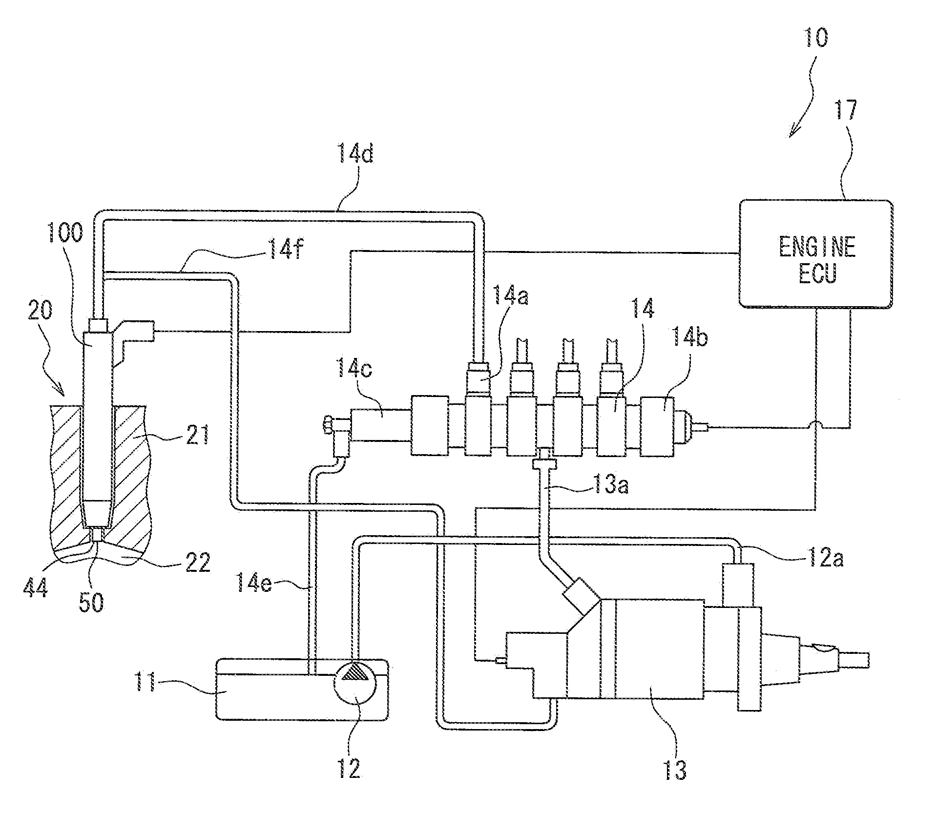
[0022]A fuel supply system 10, in which a fuel injection device 100 according to a first embodiment of the present invention is used, is shown in FIG. 1. The fuel injection device 100 of the present embodiment is a so-called direct injection fuel supply system in which fuel is directly injected into a combustion chamber 22 of a diesel engine 20 as an internal combustion engine.

[0023]The fuel supply system 10 is constructed of a feed pump 12, a high-pressure fuel pump 13, a common rail 14, an engine control device 17 (engine ECU), the fuel injection device 100, and the like.

[0024]The feed pump 12 is an electrically driven pump and is housed in a fuel tank 11. The feed pump 12 applies a feed pressure to fuel stored in the fuel tank 11, such that the feed pressure is higher than the vapor pressure of the fuel. The feed pump 12 is connected to the high-pressure fuel pump 13 with a fuel pipe 12a and supplies the liquid-state fuel, which has a predetermined feed pressure applied thereto, ...

second embodiment

[0068]A second embodiment of the present invention will be described with reference to FIG. 7. The second embodiment shown in FIG. 7 is a modification example of the above-described first embodiment. A fuel injection device 200 of the second embodiment includes a nozzle needle 260, an orifice plate 246 and a floating plate 270, which correspond to the nozzle needle 60, the orifice plate 46 and the floating plate 70 of the above-described first embodiment, respectively. In addition, in the fuel injection device 200, a plate spring 276 is provided to bias the floating plate 270 to the side of an opening wall surface 290 of the orifice plate 246. First, in the nozzle needle 260, a spring housing portion 262 is formed to house one end portion of the plate spring 276. The spring housing portion 262 is a cylindrical hole formed coaxially with the nozzle needle 260 in the central portion in the radial direction of the pressure receiving surface 261 of the nozzle needle 260.

[0069]According ...


PUM


Abstract

In a fuel injection device, a pressing surface of a pressing member presses an opening wall surface to interrupt communication between an inflow port and a pressure control chamber when communication between an outflow port and a return channel is made by a pressure control valve, and the pressing surface of the pressing member is displaced and separated from the opening wall surface to open the inflow port of the opening wall surface to the pressure control chamber when the communication between the outflow port and the return channel is interrupted by the pressure control valve. One of the pressing surface of the pressing member and the opening wall surface of the control body is provided with an inflow depressed portion and an outflow depressed portion partitioned from each other, and a depressed dimension of the inflow depressed portion is larger than a depressed dimension of the outflow depressed portion.

Description

CROSS REFERENCE TO RELATED APPLICATION[0001]This application is based on Japanese Patent Application No. 2010-068806 filed on Mar. 24, 2010, the contents of which are incorporated herein by reference in its entirety.FIELD OF THE INVENTION[0002]The present invention relates to a fuel injection device that opens and closes a valve portion to control an injection of supply fuel supplied form a supply channel, and that discharges a portion of the supply fuel to a return channel based on the control.BACKGROUND OF THE INVENTION[0003]There has been known a fuel injection device including a control body, which has a pressure control chamber, and a valve member for opening and closing a valve portion in response to the pressure of fuel in the pressure control chamber. In the fuel injection device, the pressure control chamber of the control body has an inflow port and an outflow port opened therein. The inflow port is a port through which fuel flowing through a supply channel flows into the ...

Claims


Application Information

Patent Timeline
Patent Type & Authority Applications(United States)
IPC IPC(8): F02M61/00
CPCF02M47/027
Inventor FUKUTA, YUKIHIROYAMASHITA, TSUKASA
Owner DENSO CORP
Why Eureka
Try Eureka