Ionization Gauge Having Electron Multiplier Cold Emission Source

a technology of electron multiplier and emission source, which is applied in the direction of vacuum gauge, fluid pressure measurement, instruments, etc., can solve the problems of reducing the emission characteristics of electron sources, gauging and electron sources, and reducing the operational life, so as to reduce the number of electrons generated and reduce the operational life

Active Publication Date: 2011-09-29
MKS INSTR INC
View PDF42 Cites 19 Cited by
  • Summary
  • Abstract
  • Description
  • Claims
  • Application Information

AI Technical Summary

Benefits of technology

[0006]The operational lifetime of a typical BA ionization gauge is approximately ten years when the gauge is operated in benign environments. However, these same gauges and electron sources (filaments) can fail in minutes or hours when operated at too high a pressure or in gas types that degrade the emission characteristics of the electron source. Well known examples of such filament interactions, leading to decreased operational lifetime are due to chemical reactions with some gaseous environments, and can lead to degradation of the electron emission properties of the oxide coating on the filament. Degradation of the oxide coating dramatically reduces the number of electrons generated by the filament. Tungsten filaments also experience degradation of emission properties under these conditions, and additionally exposure to water vapor at too high a pressure results in the complete burnout of a tungsten filament. A reliable cold electron emitter would avoid these known problems. There is a need in the art for a cold electron emitter ionization gauge that will function without the drawbacks of the BA ionization gauge, without changing the chemical composition of the gas species in the chamber, and without degrading the gauge.

Problems solved by technology

However, these same gauges and electron sources (filaments) can fail in minutes or hours when operated at too high a pressure or in gas types that degrade the emission characteristics of the electron source.
Well known examples of such filament interactions, leading to decreased operational lifetime are due to chemical reactions with some gaseous environments, and can lead to degradation of the electron emission properties of the oxide coating on the filament.
Tungsten filaments also experience degradation of emission properties under these conditions, and additionally exposure to water vapor at too high a pressure results in the complete burnout of a tungsten filament.

Method used


Image

  • Ionization Gauge Having Electron Multiplier Cold Emission Source
  • Ionization Gauge Having Electron Multiplier Cold Emission Source
  • Ionization Gauge Having Electron Multiplier Cold Emission Source

Examples


Embodiment Construction

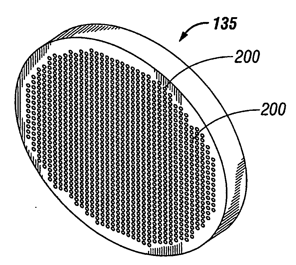
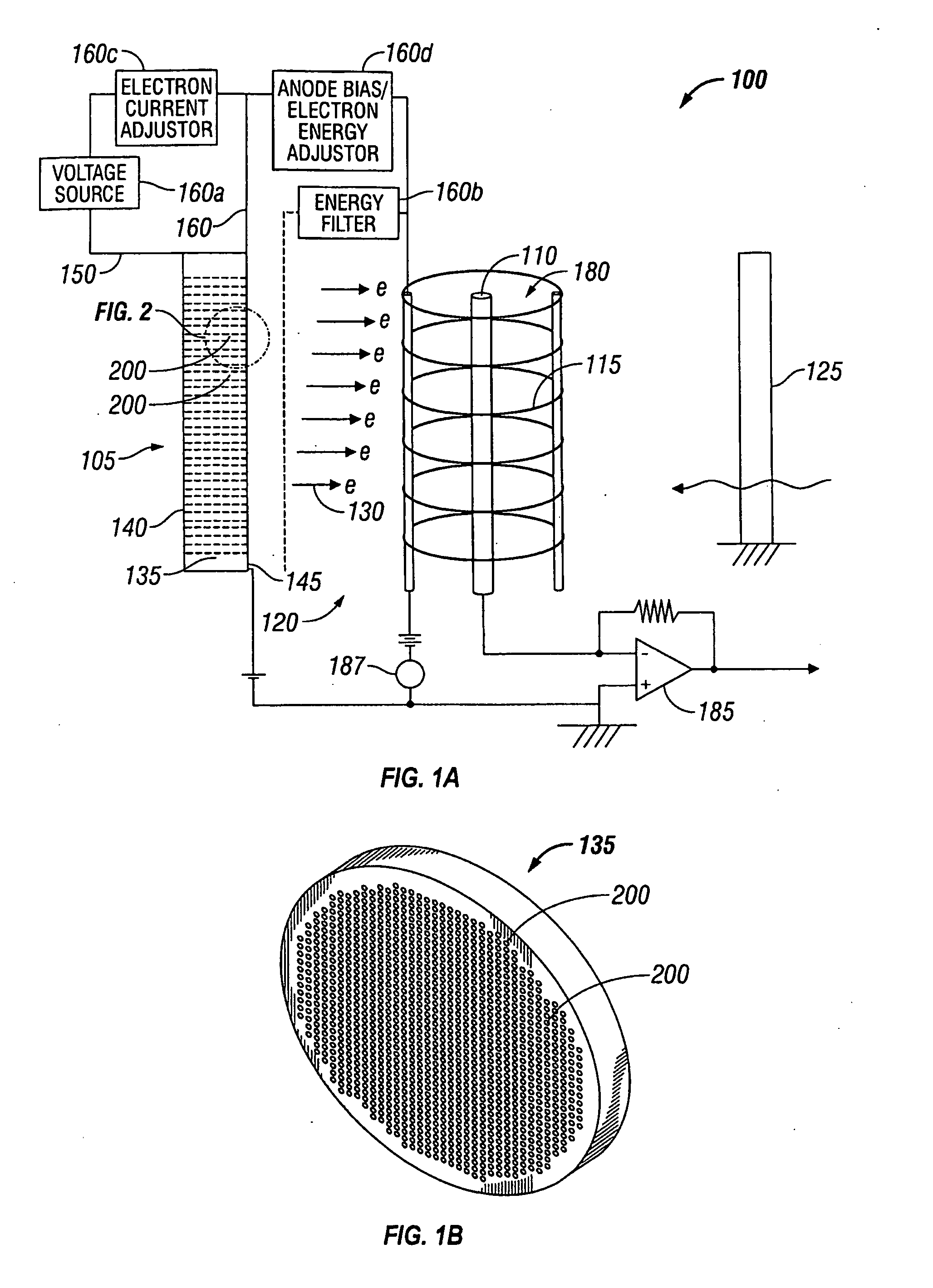
[0026]A description of preferred embodiments of the invention follows. Generally, as shown in FIG. 1A, an ionization gauge 100 of the present disclosure includes an electron generator array 105, an ion collector electrode 110, and an anode 115. Although the ionization gauge 100 is shown with an anode 115, and collector electrode 110, these components are not needed in all embodiments of the invention as described below and various different ionization gauge configurations are possible. In one embodiment, the ionization gauge 100 is a non-Bayard-Alpert type gauge, or a cold electron emitter ionization gauge, and does not include any hot cathode filament as the electron source for the gauge 100. Instead, ionization gauge 100 is formed in a cold electron emitter gauge configuration and includes a source for generating seed electrons together with a source for multiplying the seed electrons collectively shown as reference numeral 105 as the electron generating array.

[0027]Ionization gau...


PUM

PropertyMeasurementUnit
temperatureaaaaaaaaaa
sizeaaaaaaaaaa
voltageaaaaaaaaaa

Abstract

An ionization gauge includes an electron generator array that includes a microchannel plate that includes an electron generating portion of the microchannel plate comprising a source for generating seed electrons and an electron multiplier portion of the microchannel plate, responsive to the seed electrons generated by the electron generating portion, that multiplies the electrons. The ionization gauge includes an ionization volume in which the electrons impact a gaseous species, and a collector electrode for collecting ions formed by the impact between the electrons and gas species. The collector electrode can be surrounded by the anode, or the ionization gauge can be formed with multiple collector electrodes. The source of electrons can provide for a spontaneous emission of electrons, where the electrons are multiplied in a cascade.

Description

RELATED APPLICATION[0001]This application claims the benefit of U.S. Provisional Application No. 61 / 008,185, filed on Dec. 19, 2007. The entire teachings of the above application are incorporated herein by reference.BACKGROUND OF THE INVENTION[0002]Bayard-Alpert (BA) ionization gauges are the most common non-magnetic means of measuring very low pressures and have been widely used worldwide since being disclosed in 1952 in U.S. Pat. No. 2,605,431, which is herein incorporated by reference in its entirety.[0003]A typical ionization gauge includes an electron source, an anode, and an ion collector electrode. For the BA gauge, the electron source is located radially outside of an ionization space (anode volume) defined by the anode. The ion collector electrode is disposed within the anode volume. Electrons travel from the electron source toward and into the anode. In their travel, the electrons impact molecules and atoms of gas, constituting the atmosphere whose pressure is to be measur...

Claims


Application Information

Patent Timeline
Patent Type & Authority Applications(United States)
IPC IPC(8): G01L21/30G01N27/62
CPCG01L21/34H01J41/06G01N27/64G01N27/623
Inventor BRUCKER, GERARDO A.
Owner MKS INSTR INC
Why Eureka
Try Eureka