High power pulse generator

a generator and high-power technology, applied in the field of high-power pulse generators, can solve the problems of low system radiating efficiency, limited pulse repetition rate, and inability to radiate,

Inactive Publication Date: 2011-09-29
BAE SYST INFORMATION & ELECTRONICS SYST INTERGRATION INC
View PDF28 Cites 9 Cited by
  • Summary
  • Abstract
  • Description
  • Claims
  • Application Information

AI Technical Summary

Benefits of technology

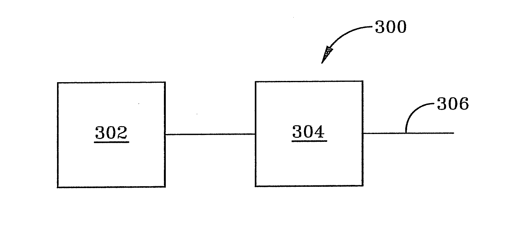
[0007]The preferred embodiment of the invention includes a pulse generator for generating a high power pulse. The high power pulse can be either a radio frequency signal or a microwave signal. The pulse generator includes a generator and a modulator unit. The generator generates a bipolar signal. The modulator unit modulates the bipolar signal with oscillating signals to generate a modulated bipolar signal with oscillating pulses. The frequency spectrum of the modulated bipolar signal contains very little to no direct current (DC) components.

Problems solved by technology

The energy stored in these direct current and very low frequency components is useless (cannot be radiated).
Since the portion of energy stored in these components substantially exceeds the energy stored in RF components, the radiating efficiency of system is very low.
Furthermore, the pulse repetition rate is limited by thermal and cooling issues, as well as the charge rate available into the high voltage video pulse generator.
Moreover, high-voltage Blumlein generators that usually employ spark-gap switches cannot be recharged in a short time period (sub-nanosecond range).
Therefore, it is generally not possible in an existing system based on NLTL modulators to generate a train of damped sinusoids to provide high output energy in short period of time.

Method used


Image

  • High power pulse generator
  • High power pulse generator
  • High power pulse generator

Examples


Embodiment Construction

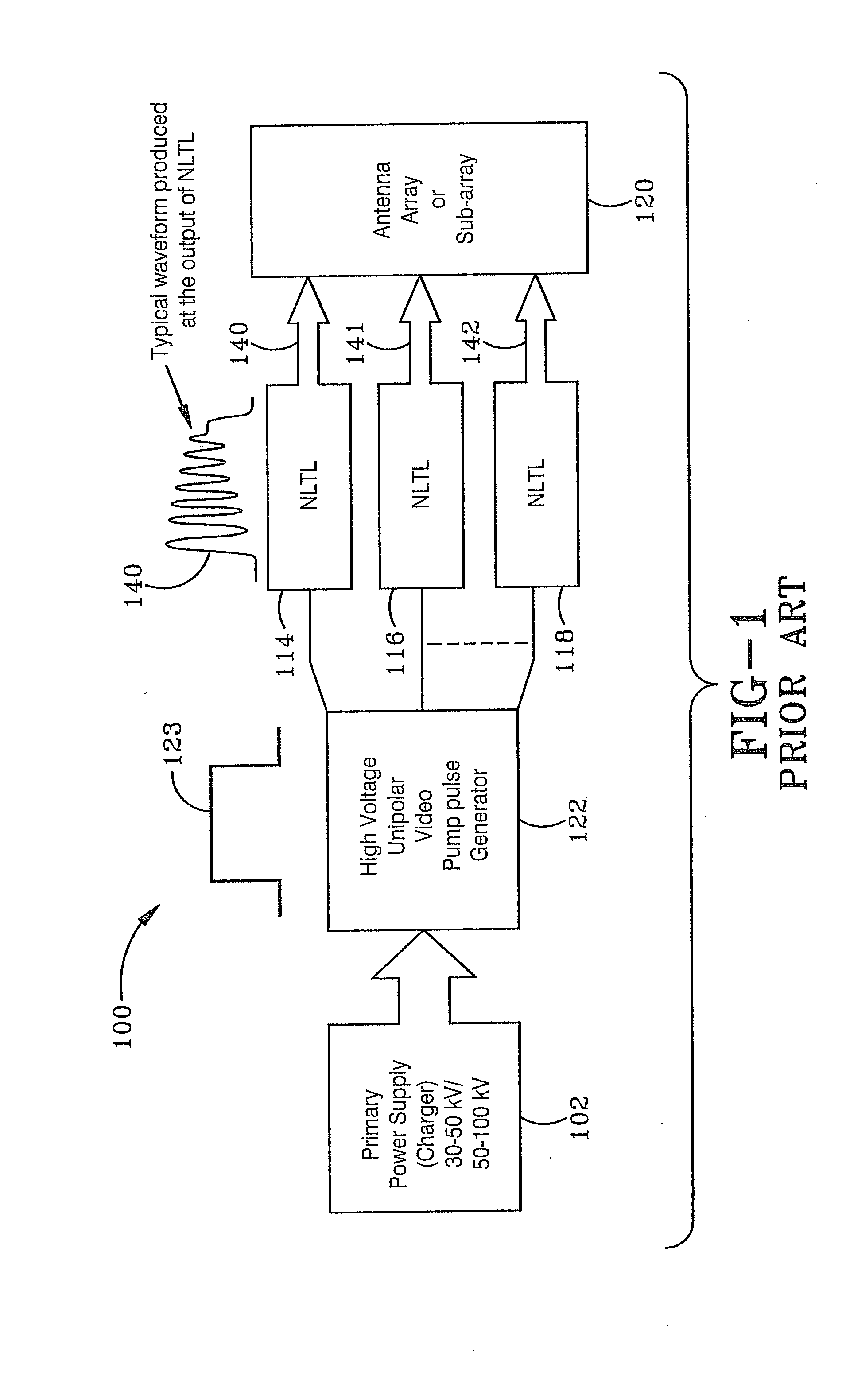
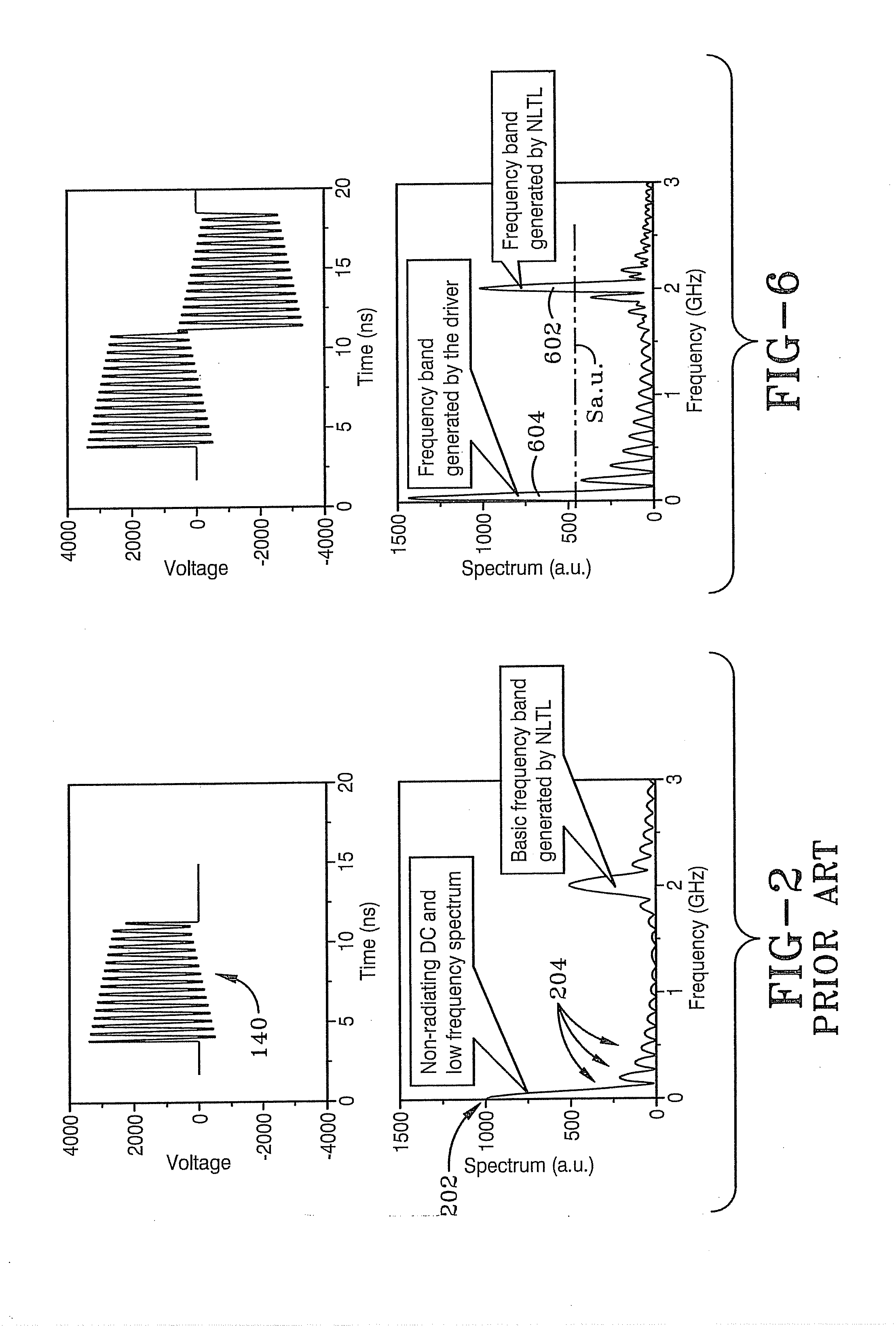
[0027]FIG. 1 illustrates an exemplary prior art system 100. The system 100 includes a primary power supply 102 to power a high voltage unipolar pulse pump generator 122 (for example, Blumlein pulse generator) to generate a unipolar signal 123. The signal 123 is provided to an array of NLTL modulators 114, 116 and 118. The NLTLs 114, 116 and 118 produce corresponding unipolar dampened sinusoidal outputs 140, 141 and 142. These outputs 140, 141 and 142 are input to an antenna array or sub-array 120. As shown in FIG. 2, the frequency spectrum of these outputs 140, 141 and 142 have a rather large DC component 202 as well as low frequency components 204.

[0028]FIG. 3 illustrates the preferred embodiment of the invention in a first configuration as a pulse generator 300. This pulse generate 300 can be used to generate high power microwave pulses and / or high power radio frequency pulses. The pulse generator 300 includes a generator 302 and a modulator unit 304. The generator 302 generates a...


PUM


Abstract

A systems, pulse generators, apparatus and methods for generating a high power signal are presented. A pulse generator includes a generator and a modulator unit. The generator generates a bipolar signal. The modulator unit modulates the bipolar signal with oscillating signals to generate a modulated bipolar signal with oscillating portions. The frequency spectrum of the modulated bipolar signal contains very little to no direct current (DC) component.

Description

CROSS REFERENCE TO RELATED APPLICATION[0001]This application claims priority from U.S. Provisional Patent Application Ser. No. 61 / 317,772 filed Mar. 26, 2010; the disclosure of which is incorporated herein by reference.BACKGROUND OF THE INVENTION[0002]1. Field of Invention[0003]The current invention relates generally to apparatus, systems and methods for generating radio frequency signals. More particularly, the apparatus, systems and methods relate to generating high power radio frequency (RF) pulses or high power microwave pulses. Specifically, the apparatus, systems and methods provide for generating a high power RF or microwave pulse based on a bipolar signal driver.[0004]2. Description of Related Art[0005]Various techniques based on different types of modulators of low frequency signals have been proposed as sources of RF or microwave radiation. The most successful implementations of this concept in high power microwave (HPM) systems to date have been realized by employing vari...

Claims


Application Information

Patent Timeline
Patent Type & Authority Applications(United States)
IPC IPC(8): H04L27/00
CPCH03K5/12H04K2203/34H04K3/62H04K3/42
Inventor LONDON, SIMON Y.KOZYREV, ALEXANDER
Owner BAE SYST INFORMATION & ELECTRONICS SYST INTERGRATION INC
Why Eureka
Try Eureka