Control rod transfer device

a technology for controlling rods and transfer devices, which is applied in the direction of nuclear engineering, greenhouse gas reduction, nuclear elements, etc., can solve the problems of awkward movement of the transfer device, difficulty in reinserting within a second fuel assembly without the aid of means,

Active Publication Date: 2011-09-29
WESTINGHOUSE ELECTRIC CORP
View PDF24 Cites 14 Cited by
  • Summary
  • Abstract
  • Description
  • Claims
  • Application Information

AI Technical Summary

Benefits of technology

[0009]The foregoing object is achieved by a transfer device for moving a control rod assembly between fuel assemblies using an overhead crane. The control rod assembly has a plurality of spaced control rods which are supported from an overhead web or spider frame which aligns the control rod with guide thimble tubes in the fuel assemblies in which the control rods are designed to be inserted. In accordance with this embodiment, the transfer device includes an upper latch tube assembly having a longitudinal axis. An elongated inner member is slidably supported within the upper latch tube assembly is operable to telescope substantially coaxially with the longitudinal axis. A gripper assembly is supported from the elongated inner member and has an actuation arm reciprocably slidably supported within the elongated inner member to move substantially along the longitudinal axis a selected distance to actuate a gripper at one end of the gripper assembly. Another end of the gripper assembly is connected to an end of the elongated inner member which at another end includes a bail which is adapted to be attached to an overhead crane. An interlock assembly is attached to the upper latch tube assembly and selectively couples the elongated in...

Problems solved by technology

Because the poison rods, which are approximately 12 to 14 feet (3.66 to 4.27 meters) long, are only connected by the web or spider located at the top of the poison rod assembly, the lower end of the poison rods move freely, and, as such, can be ...

Method used


Image

  • Control rod transfer device
  • Control rod transfer device
  • Control rod transfer device

Examples


Embodiment Construction

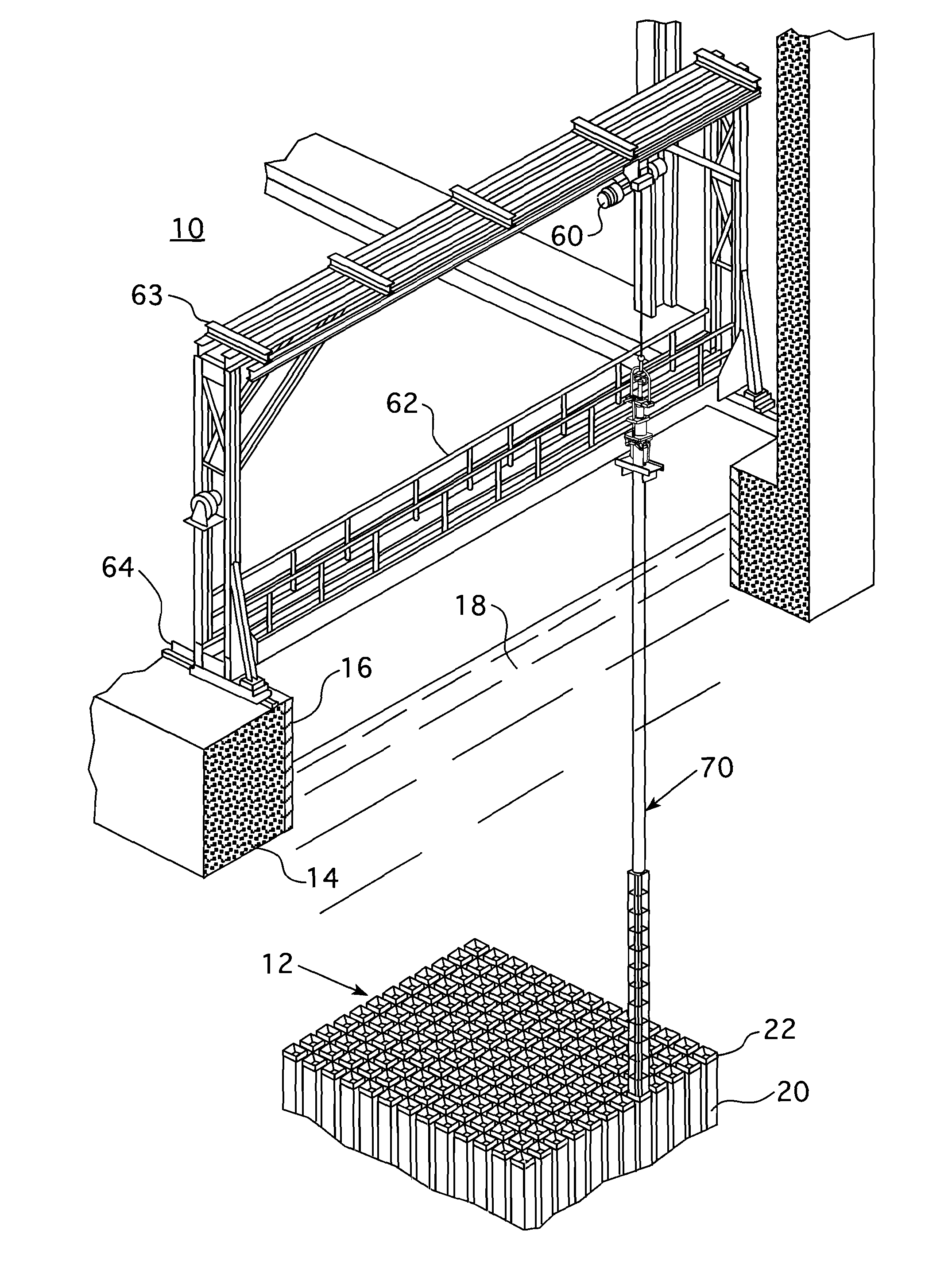
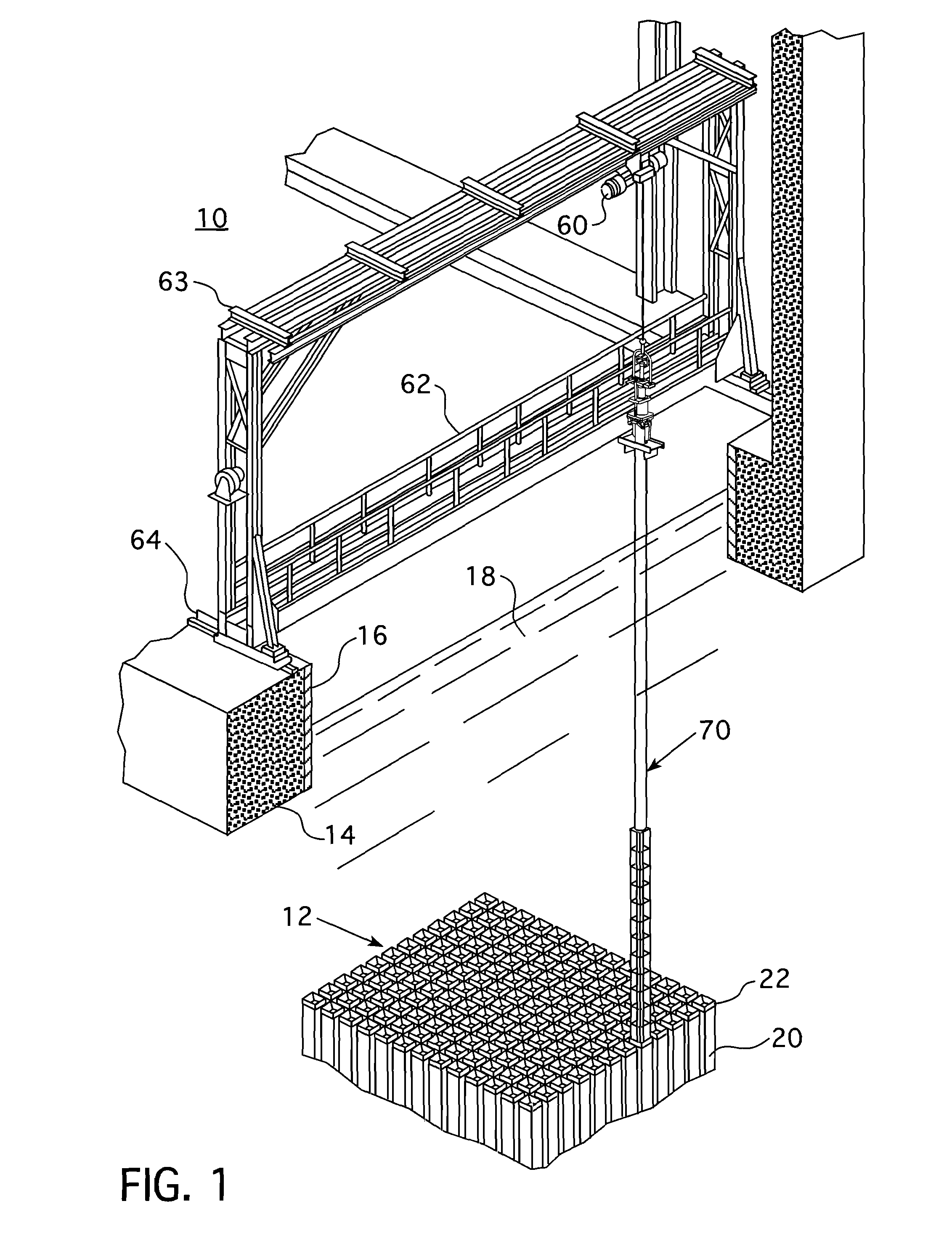
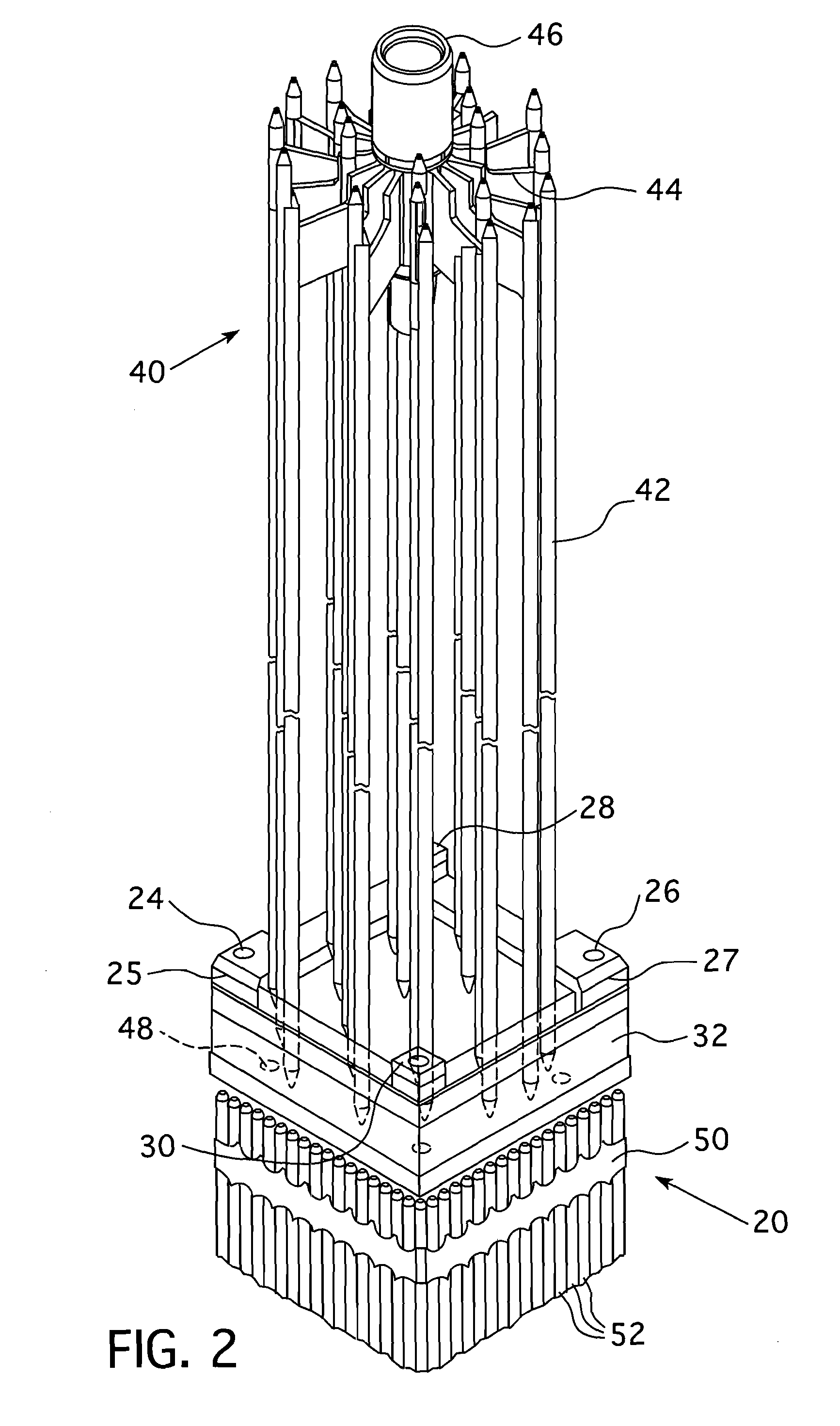
[0027]Referring to FIG. 1, there is illustrated a spent fuel storage pool 10 which contains a plurality of spent nuclear fuel racks 12. The spent fuel pool 10 is a sealed enclosure comprised of concrete 14 and a sealed metallic liner 16. The spent fuel pool 10 is filled with a shielding medium, such as water containing boric acid 18. Each fuel rack 12 includes a plurality of vertically oriented spaced apart fuel cells 20. Each cell 20 is sized to received a fuel assembly 50 (described below). Each cell 20 has a metallic can 22 affixed to the top of the cell 20. The can 22 may include a square funnel to guide a fuel assembly 50 into its storage position. As shown in FIG. 2, the can 22 includes two bores 24, 26 in raised plates 25, 27 at diagonally opposite corners. The remaining corners of the can 22 define standoff plates 28, 30. However, it should be appreciated that the fuel assembly top nozzle may have the bores 24, 26, raised plates 25, 27 and standoff plates 28, 30, without dep...


PUM


Abstract

A telescoping rod control cluster assembly change tool for moving control rod assemblies among fuel assemblies in a nuclear facility. The operation of the tool is completely mechanical and the telescoping feature enables the tool to have a relatively low profile when it is being moved and stored without housing a control rod assembly. Rigidly supported alignment cards guide a gripper that attaches to the control rod assembly as the control rod assembly is withdrawn into the tool with the alignment cards preventing any lateral or rotational movement of the gripper.

Description

CROSS REFERENCE TO RELATED APPLICATIONS[0001]This application claims priority to Provisional Application Ser. No. 61 / 316,956, filed Mar. 24, 2010, Attorney Docket NSD2010-003.BACKGROUND[0002]1. Field[0003]This invention relates to a device for transporting control rod assemblies between fuel assemblies in a facility associated with a nuclear power generation plant and, more specifically, to a device for transferring control rod assemblies among fuel assemblies that uses an overhead crane as its primary lifting mechanism.[0004]2. Related Art[0005]Fuel for a nuclear reactor used to create steam and, ultimately, electricity, generally is in the form of fuel rods containing a fissile material. When fuel rods are being stored, the fuel rods are typically supported in nuclear fuel assemblies arranged as spaced parallel arrays. Fuel assemblies are stored in racks in a protective medium, such as water containing boric acid. In addition to the fuel rods, poison rods and / or water displacer ro...

Claims


Application Information

Patent Timeline
IPC IPC(8): G21C7/12
CPCG21C7/117G21C19/32G21C19/115G21C19/105Y02E30/30G21C7/08
Inventor STEFKO, DAVID J.HARTLE, JASON A.DEAH, CRAIG
Owner WESTINGHOUSE ELECTRIC CORP
Why Eureka
Try Eureka