Battery pack

a battery pack and chamber technology, applied in the field of batteries, can solve the problems of difficult to achieve binding force sufficient to integrate all of the battery cells, difficult to manage a strict size relation between the battery cell chamber and the battery cell, etc., and achieve the effect of small rigidity, easy deflection and sufficient binding for

Inactive Publication Date: 2011-09-29
DENSO CORP
View PDF2 Cites 29 Cited by
  • Summary
  • Abstract
  • Description
  • Claims
  • Application Information

AI Technical Summary

Benefits of technology

[0010]According the above battery pack, the rigidity of the connection member against the load acting along the stack direction is smaller the rigidity of the surface pressing member. Thus, when an external force acts on the side surfaces, normal to the stack direction “X”, of the surface pressing members to bind the battery pack with a binding force compressing the battery pack from both sides of the battery pack along the stack direction “X”, the connection member with a small rigidity can be easily deflected. In this way, it is possible attain close contact between the battery cells and the surface pressing members, and it is possible to bind all of the stacked battery cells in a reliable manner. Therefore, the battery pack can adapt a battery cell thickness variation and can obtain the binding force sufficient to integrate the multiple battery cells.

Problems solved by technology

In practice, the size of battery cell has a manufacturing variation, and it is difficult to manage a strict size relation between the battery cell chamber and the battery cell.
In this case, it is impossible to obtain a binding force sufficient to integrate all of the battery cells.

Method used


Image

  • Battery pack
  • Battery pack
  • Battery pack

Examples


first embodiment

[0032]A battery pack according to embodiments of the present invention can be used in, for example, a hybrid vehicle, which uses an internal combustion engine and a motor energized by an electric power charged in a battery as a driving power source thereof, an electric vehicle, which uses a motor as a driving power source thereof, or the like. A battery of the battery pack is, for example, a nickel-hydride secondary battery, a lithium-ion secondary battery, an organic radical battery or the like. The battery received in a casing may be arranged in a space underneath a seat of a vehicle, a space between a backseat and a trunk room, a space between a driver seat and a front passenger seat, or the like.

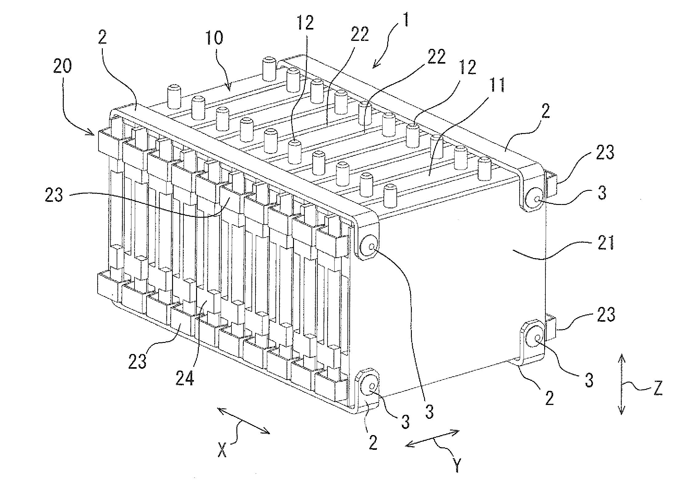
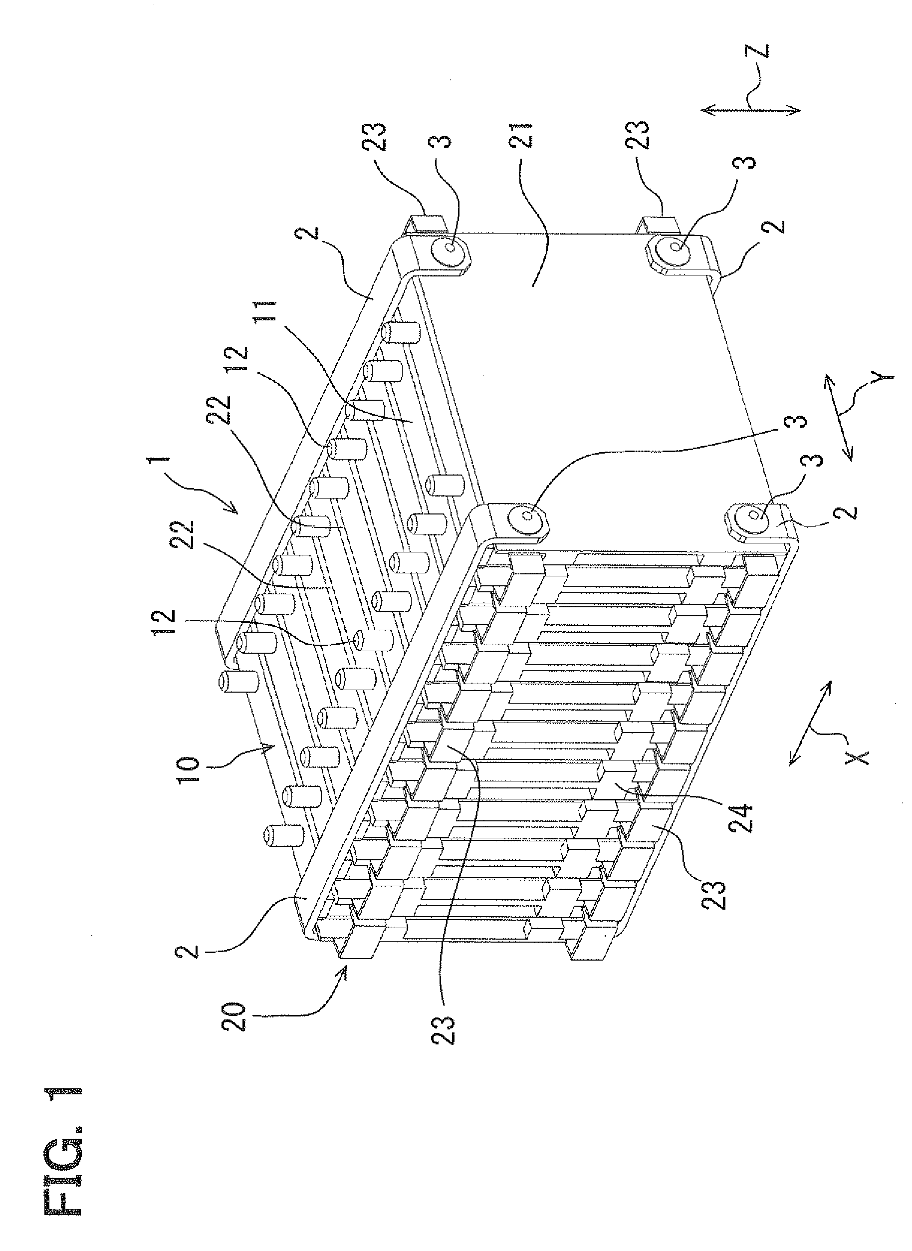
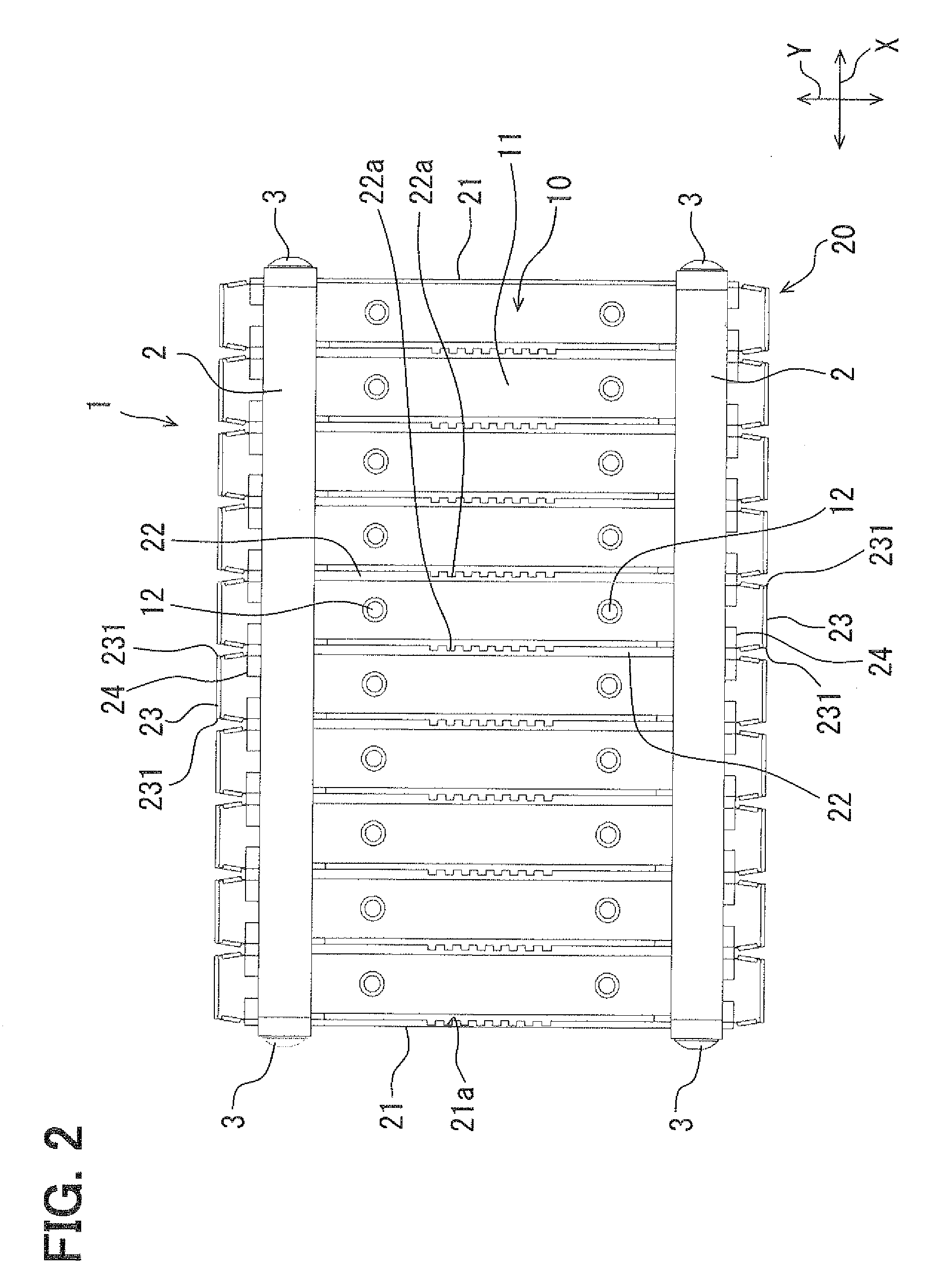
[0033]The first embodiment will be described below with reference to FIGS. 1 to 8. FIG. 1 is a perspective view of a battery pack 1 of the first embodiment. FIG. 2 is a plan view of the battery pack 1. FIG. 4 is a side view of the battery pack 1 viewed in a longitudinal direction “Y”. FI...

second embodiment

[0059]A battery pack 1A provided with a battery holder device 20A of a second embodiment will be described below with reference to FIGS. 9 to 12. FIG. 9 is a perspective view of the battery pack 1A of the second embodiment. FIG. 10 is a side view of the battery holder device 20A. FIG. 11 is a plan view of the battery holder device 20A. FIG. 12 is a side view of the battery holder device 20A viewed in the longitudinal direction “Y”. As shown in FIGS. 9 to 12, a direction in which multiple battery cells 11 are stacked and arranged is defined as the stack direction “X”. A direction in which each rectangular battery cell 11 is elongated is defined as a longitudinal direction “y” A direction perpendicular to both of the stack direction “X” and the longitudinal direction. “Y” is defined as a height direction “Z” (also called a vertical direction “Z” or an upper / lower direction “Z”).

[0060]The battery holder device 20A of the second embodiment is different from the battery holder device 20 ...

third embodiment

[0068]A battery pack 1B with a battery holder device 20B of a third embodiment will be described below with reference to FIGS. 13 to 14. FIG. 13 is a perspective view of the battery pack 1B before a busbar 274 is mounted to the terminal parts 12 of the battery cells 11. FIG. 14 is a perspective view of the battery pack 1B after the busbar 274 is mounted to the terminal parts 12 of the battery cells 11. As shown in FIGS. 13 to 14, a direction in which multiple battery cells 11 are stacked and arranged is defined as the stack direction “X”. A direction in which each rectangular battery cell 11 is elongated is defined as a longitudinal direction “Y”. A direction perpendicular to both of the lamination direction “X” and the longitudinal direction “Y” is defined as a height direction “Z” (also called a vertical direction “Z”).

[0069]The battery holder device 20B of the present embodiment is different from the battery holder device 20 of the first embodiment in that the battery holder devi...


PUM

PropertyMeasurementUnit
rigidityaaaaaaaaaa
lengthaaaaaaaaaa
thicknessaaaaaaaaaa

Abstract

A battery pack is disclosed. The battery pack includes angular-shaped battery cells stacked in a stack direction and a battery holder device. The battery holder device presses side surfaces of the battery cells with a load acting along the stack direction. The battery holder device integrally includes multiple surface pressing members each interposed between adjacent battery cells and multiple connection members each connecting adjacent surface pressing members. Rigidity of each connection member against the load acting along the stack direction is smaller than rigidity of each surface pressing member against the load acing along the stack direction.

Description

CROSS REFERENCE TO RELATED APPLICATION[0001]The present application is based on and claims priority to Japanese Patent Application No. 2010-68811 filed on Mar. 24, 2010 and Japanese Patent Application No. 2011-036160 filed on Feb. 22, 2011, disclosures of which are incorporated herein by reference.BACKGROUND OF THE INVENTION[0002]1. Field of the Invention[0003]The present invention relates to a battery pack, which includes an assembly of multiple stacked battery cells.[0004]2. Description of Related Art[0005]Patent Document 1 describes a conventional battery pack in which multiple flat battery cells are electrically connected in series with each other and are stacked. Multiple interlayer members are interposed between the stacked battery cells. The multiple interlayer members arranged between the battery cells are connected with each other via heat conduction members having a high thermal conductivity. The heat conduction members and the multiple interlayer members are integrally fo...

Claims


Application Information

Patent Timeline
Patent Type & Authority Applications(United States)
IPC IPC(8): H01M2/10H01M50/209H01M50/227H01M50/264H01M50/289
CPCH01M2/1077H01M2220/20H01M10/0481H01M10/0413Y02E60/10H01M50/209H01M50/227H01M50/264H01M50/289
Inventor WATANABE, MASAYUKIINOUE, HISATOMURAKAMI, FUMIAKIHIRAIWA, NAOKIKUZUHARA, HUMIHIRO
Owner DENSO CORP
Why Eureka
Try Eureka