Digital, Small Signal and RF Microwave Coaxial Subminiature Push-on Differential Pair System

Active Publication Date: 2011-09-29
CORNING OPTICAL COMM LLC
View PDF33 Cites 53 Cited by
  • Summary
  • Abstract
  • Description
  • Claims
  • Application Information

AI Technical Summary

Benefits of technology

[0013]Accordingly, a simple connector is disclosed herein that can easily be produced from a small number of components. The connector preferably forms a reliable electrical

Problems solved by technology

However, when confronted with two electrical conductors in

Method used


Image

  • Digital, Small Signal and RF Microwave Coaxial Subminiature Push-on Differential Pair System
  • Digital, Small Signal and RF Microwave Coaxial Subminiature Push-on Differential Pair System
  • Digital, Small Signal and RF Microwave Coaxial Subminiature Push-on Differential Pair System

Examples


Embodiment Construction

[0029]Reference will now be made in detail to the present preferred embodiment(s) of the invention, examples of which are illustrated in the accompanying drawings. Whenever possible, the same reference numerals will be used throughout the drawings to refer to the same or like parts.

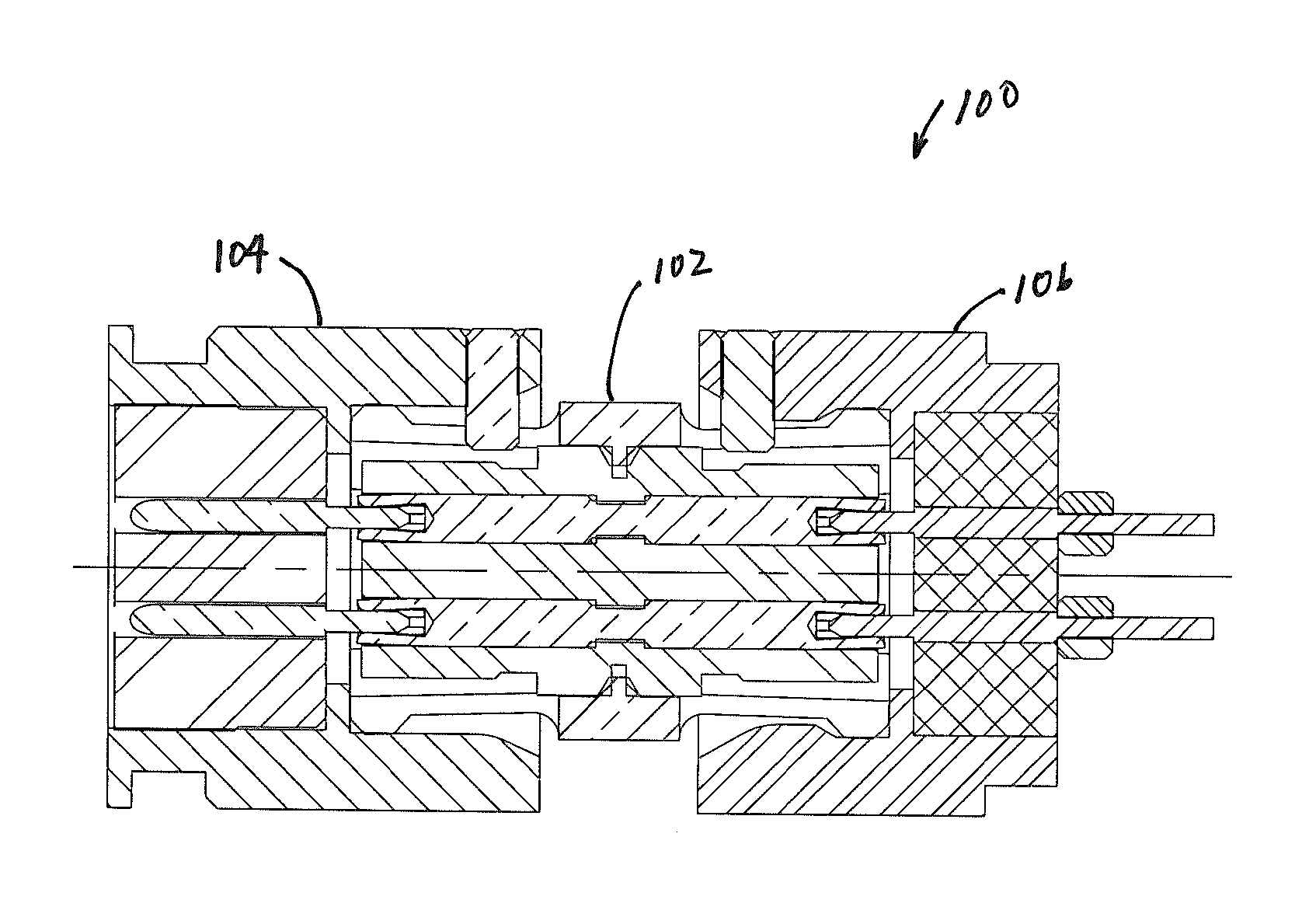
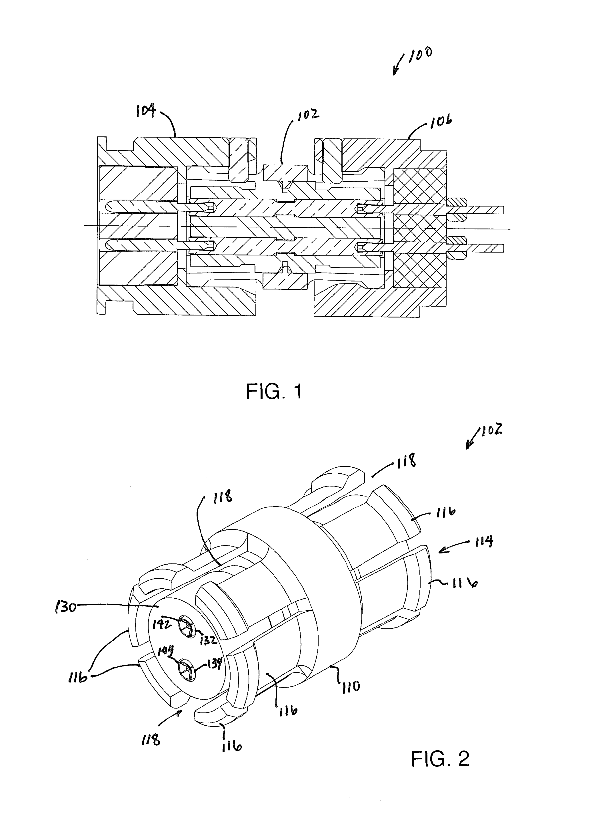
[0030]Referring to FIGS. 1-13, a connector assembly 100 includes a differential interconnect 102, a first connector 104, and a second connector 106. Generally, the connector assembly 100 allows for the connection, and in particular, the blind mating of the first connector 104 and the second connector 106. As can be seen from the figures, as well as being described above, the connector assembly 100 provides for a quick way to engage and disengage differential pair interconnects that use push-on technology.

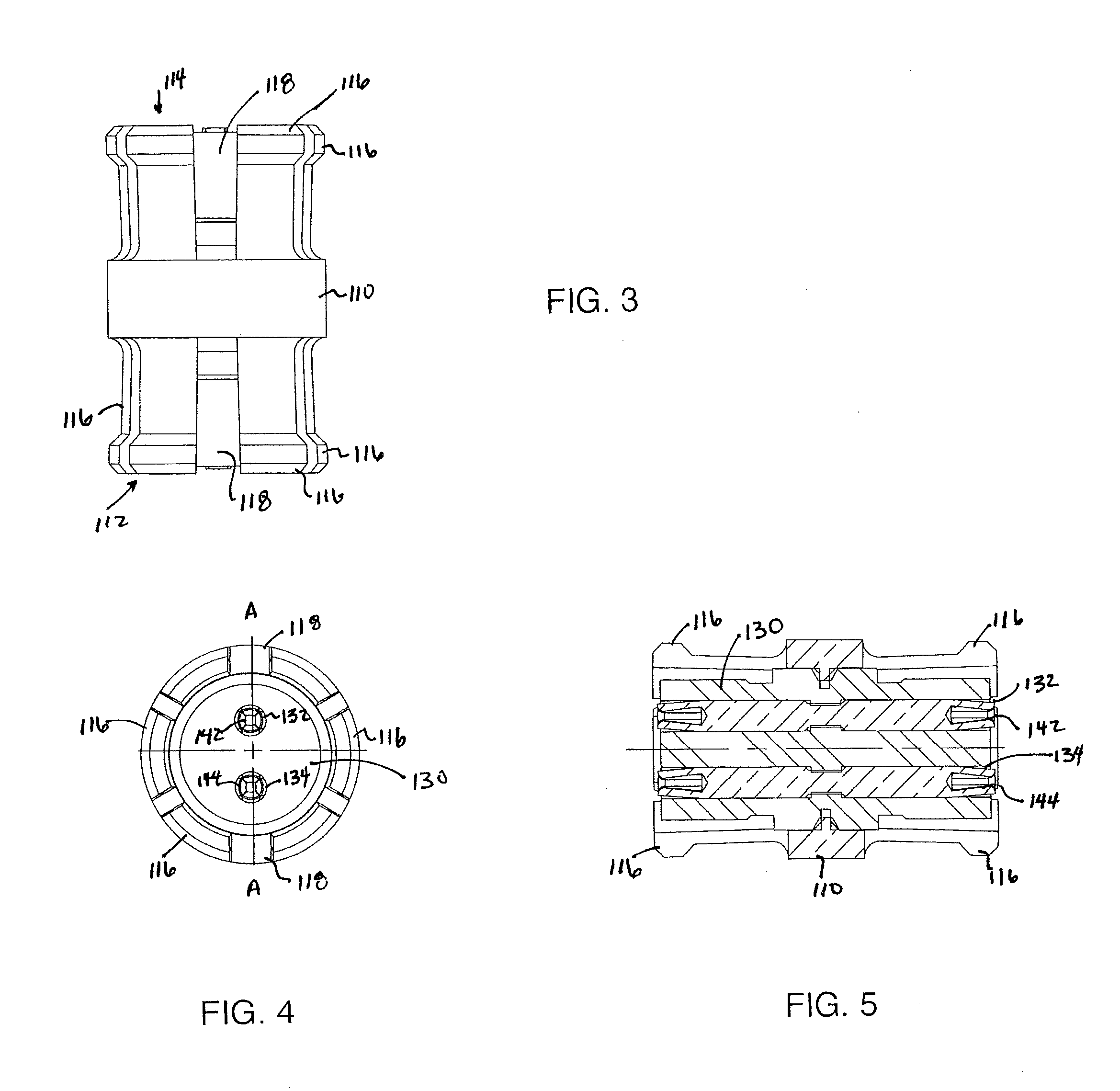
[0031]Turning now to FIGS. 2-5, the differential interconnect 102, which is a push-on high frequency differential interconnect, includes a tubular body 110. The tubular body 110 has at either end 112, 114...


PUM


Abstract

The differential pair system includes a push-on high frequency differential interconnect and push-on high frequency differential connector. The system allows for blind mating of the two components, using a keying system for the two electrical conductors to be axially and radially aligned.

Description

CROSS-REFERENCE TO RELATED APPLICATIONS[0001]This application claims the benefit of, and priority to U.S. Provisional Patent Application No. 61 / 318,571 filed on Mar. 29, 2010 entitled, “Digital, Small Signal and RF Microwave Coaxial Subminiature Push-On Differential Pair System”, the content of which is relied upon and incorporated herein by reference in its entirety.BACKGROUND OF THE INVENTION[0002]1. Field of the Invention[0003]The present invention relates generally to a digital, small signal and RF microwave frequency coaxial differential pair connector interconnect and connectors that includes a push-on interface.[0004]2. Technical Background[0005]Within the technical field of digital, small signal and RF microwave frequency coaxial connectors there exists a sub-set of connector interface designs engageable without the aid of external coupling mechanisms such as split keying dielectric components. These interconnect systems are known in the industry as Twin axial TNC's and BNC'...

Claims


Application Information

Patent Timeline
IPC IPC(8): H01R9/05
CPCH01R13/6277H01R31/06H01R13/6456
Inventor BURRIS, DONALD ANDREWFLAHERTY, THOMAS E.STEIN, CASEY ROY
Owner CORNING OPTICAL COMM LLC
Why Eureka
Try Eureka