
Microarray package device and method of manufacturing the same

a technology of microarray and package device, which is applied in the field of microarray package device, can solve the problems of deformation of the microarray substrate and/or the package substrate, inability to obtain reliable analysis results, and damage to the surface of the microarray or a lens of the optical scanner, so as to reduce the volume of the adhesive, reduce the contraction due to the hardening of the adhesive, and reduce the effect of volum

Active Publication Date: 2011-09-29
SAMSUNG ELECTRONICS CO LTD
View PDF10 Cites 1 Cited by
  • Summary
  • Abstract
  • Description
  • Claims
  • Application Information

AI Technical Summary

Benefits of technology

[0006]Provided are microarray package devices that may provide structural stability and reliable experimental results.
[0007]Provided are methods of manufacturing microarray package devices that may provide structural stability and reliable experimental results.

Problems solved by technology

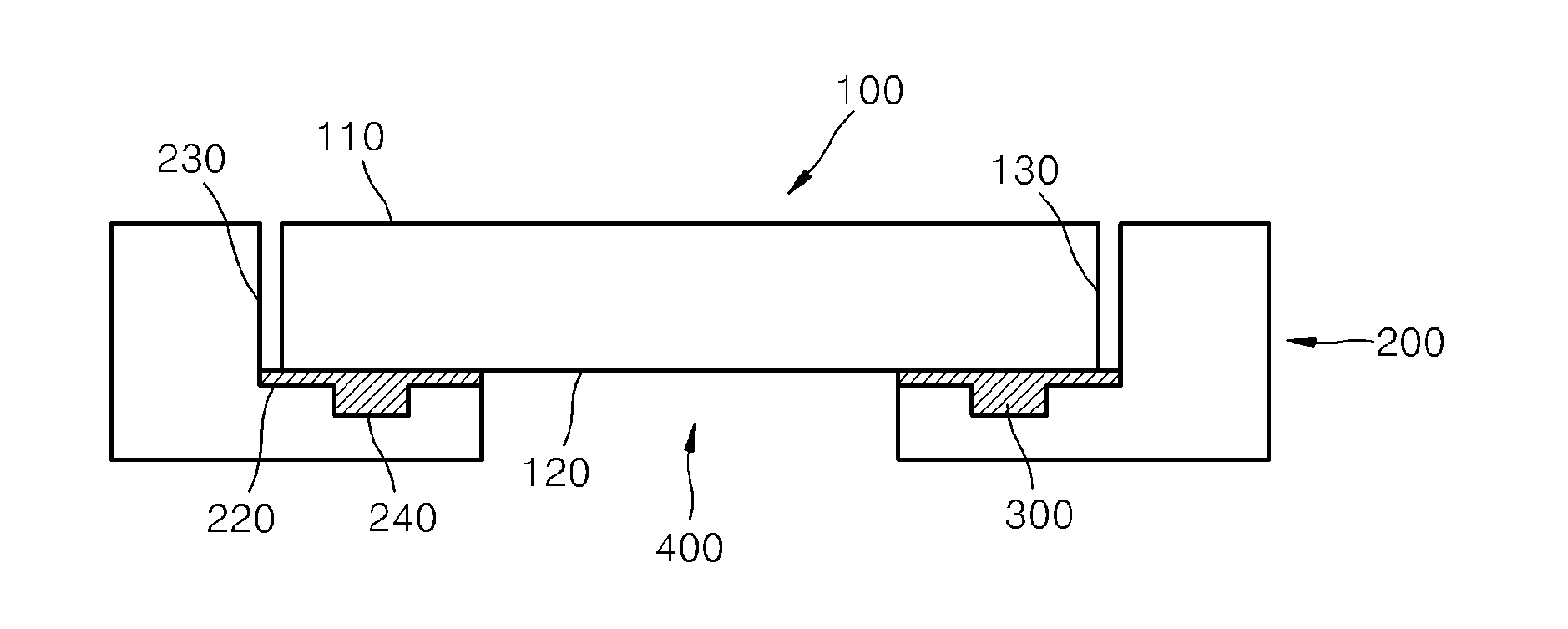
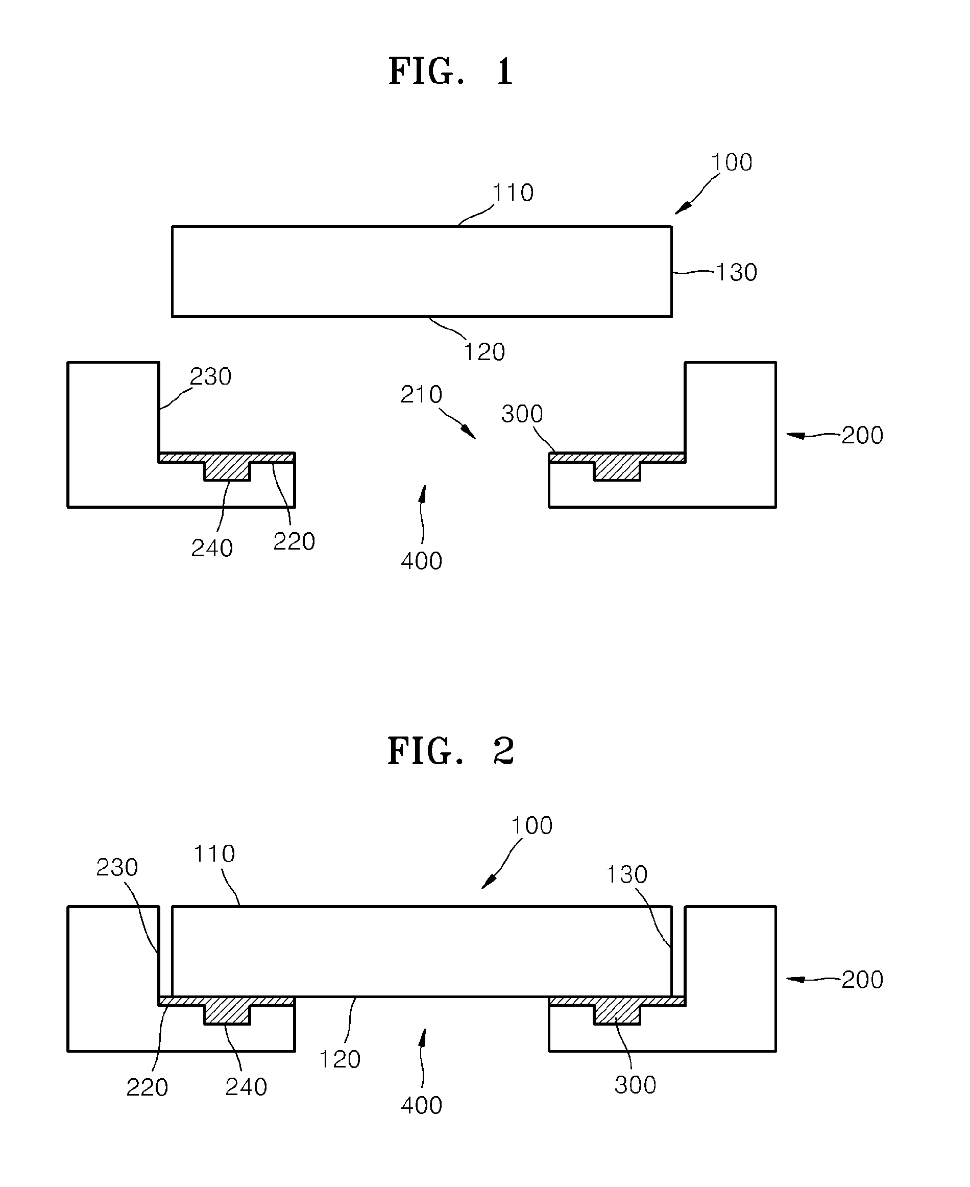
Generally, since the microarray package device is used with a fluorescent image detection system using an optical scanner, a portion of the package substrate for fixing the microarray substrate may be flush with the microarray substrate because, when a package substrate having a bottom including a protrusion is used, a surface of the microarray or a lens of the optical scanner may be damaged during the analysis of the optical scanner.
When the microarray package device deviates from a photographing region, or is inclined in a vertical direction, or when the microarray substrate is deformed due to physical external stress, an obtained image may be incorrect, e.g., warped or obfuscated, thus, a reliable analysis result may not be obtained.
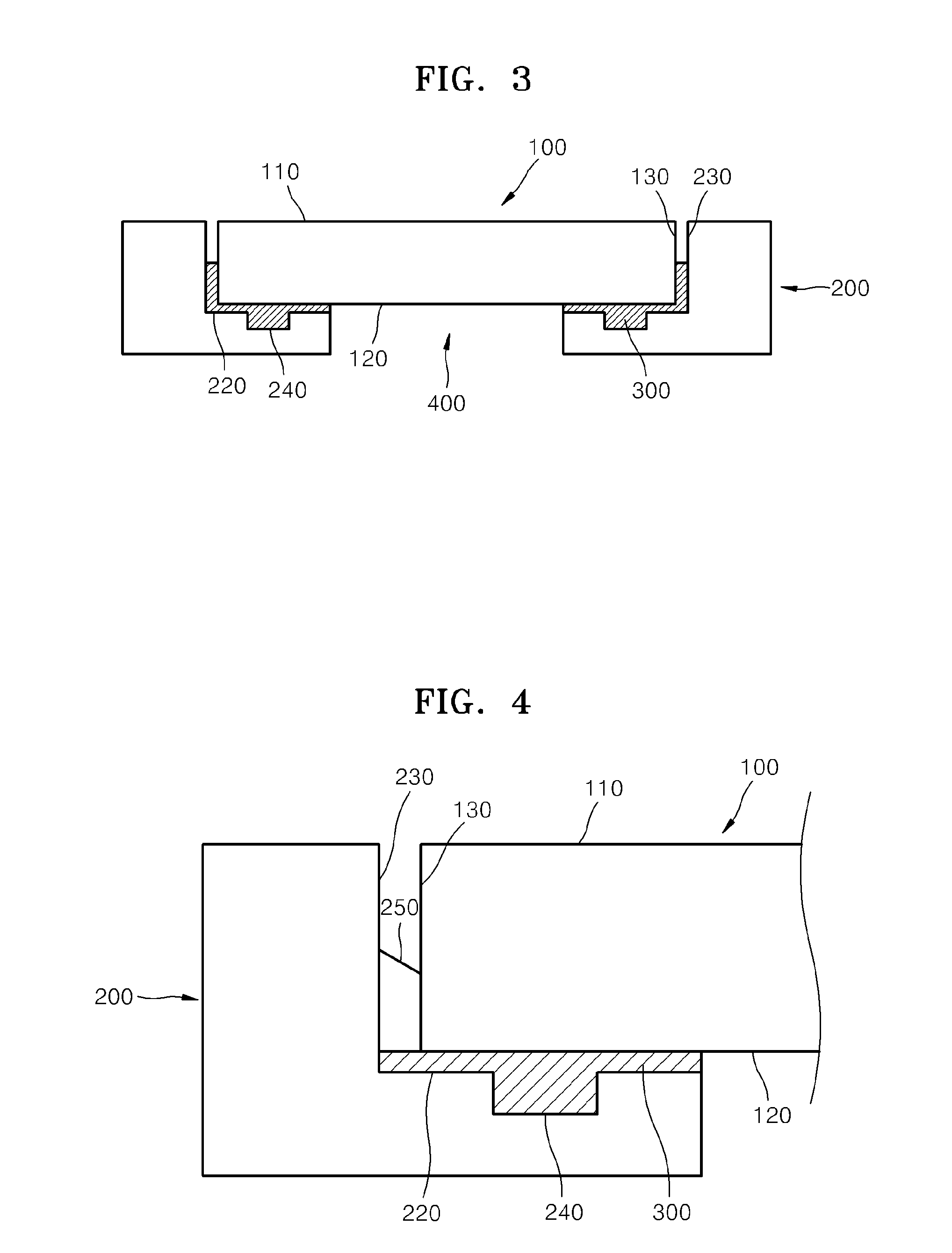
When the microarray substrate and the package substrate are adhered to each other by the adhesive, the adhesive may contract at an adhesion surface between the bottom surface of the microarray substrate and the bottom of the microarray accommodation unit since the adhesive are hardened, thereby causing deformation of the microarray substrate and / or the package substrate.
When the microarray substrate formed of silicon and the package substrate formed of plastic are adhered to each other by the UV curable adhesives, the adhesive may contract due to the hardening of the adhesive, and thus a volume of the adhesive may be reduced, thereby causing deformation of the microarray substrate and / or the package substrate.
Due to the deformation, flatness of the microarray package device may deteriorate, and thus it may be difficult to obtain reliable analyzing results of the optical scanner.
Thus, the adhesive may contract due to the hardening thereof between the side surface of the microarray substrate and the sidewall of the package substrate, and deformation of the microarray substrate and / or the package substrate may be caused.
Due to the deformation, flatness of the microarray package device may deteriorate, and thus it may be difficult to obtain reliable analyzing result of the optical scanner.
Generally, since the microarray package device is used with a fluorescent image detection system using an optical scanner, a portion of the package substrate for fixing the microarray substrate may be flush with the microarray substrate because, when a package substrate having a bottom including a protrusion is used, a surface of the microarray or a lens of the optical scanner may be damaged during the analysis of the optical scanner.
When the microarray package device deviates from a photographing region, or is severely inclined in a height direction, or when the microarray substrate is deformed due to physical external stress, an image obtained therefrom may be incorrect, thus, a reliable analysis result may not be obtained.
When the microarray substrate and the package substrate are adhered to each other by the adhesive, the adhesive may contract at an adhesion surface between the bottom surface of the microarray substrate and the bottom of the microarray accommodation unit since the adhesive is hardened, thereby causing deformation of the microarray substrate and / or the package substrate.
When the microarray substrate formed of silicon and the package substrate formed of plastic are adhered to each other by the UV curable adhesive, the adhesive may contract due to the hardening thereof, and thus a volume of the adhesive may be reduced, thereby causing deformation of the microarray substrate and / or the package substrate.
Due to the deformation, flatness of the microarray package device may be deteriorated, and thus it may be difficult to obtain reliable analyzing results from the optical scanner.

Method used


Image

  • Microarray package device and method of manufacturing the same
  • Microarray package device and method of manufacturing the same
  • Microarray package device and method of manufacturing the same

Examples


Embodiment Construction

[0044]Embodiments now will be described more fully hereinafter with reference to the accompanying drawings, in which embodiments are shown. These embodiments may, however, be embodied in many different forms and should not be construed as limited to the embodiments set forth herein. Rather, these embodiments are provided so that this disclosure will be thorough and complete, and will fully convey the scope of the disclosure to those skilled in the art. Like reference numerals refer to like elements throughout.

[0045]It will be understood that when an element is referred to as being “on” another element, it can be directly on the other element or intervening elements may be present therebetween. In contrast, when an element is referred to as being “directly on” another element, there are no intervening elements present. As used herein, the term “and / or” includes any and all combinations of one or more of the associated listed items.

[0046]It will be understood that, although the terms ...


PUM

PropertyMeasurementUnit
weightaaaaaaaaaa
temperatureaaaaaaaaaa
structural stabilityaaaaaaaaaa

Abstract

A microarray package device and a method of manufacturing the same. An effective microarray analyzing reaction is performed by using the microarray package device that provides structural stability and reliable experimental results.

Description

CROSS-REFERENCE TO RELATED APPLICATION[0001]This application claims priority to Korean Patent Application No. 10-2010-0025874, filed on Mar. 23, 2010, and all the benefits accruing therefrom under 35 U.S.C. §119, the content of which in its entirety is herein incorporated by reference.BACKGROUND[0002]1. Field[0003]The present disclosure relates to microarray package devices and methods of manufacturing the same.[0004]2. Description of the Related Art[0005]A method of analyzing a target biomaterial using a microarray has been used in various fields, for example, in studying functions of human genes, genetic analysis for diagnosing various diseases including cancer, and pharmacogenomics. A microarray is a device which includes biomaterial probes that are capable of being complementarily coupled, e.g., hybridized, to a target biomaterial, and plays a significant role in detecting and analyzing the target biomaterials. A microarray package device has been suggested for effectively analy...

Claims


Application Information

Patent Timeline
Patent Type & Authority Applications(United States)
IPC IPC(8): C40B40/00C40B50/00
CPCB01L3/508C40B60/12B01L2300/0819B01L2200/025
Inventor LEE, WOOCHANGSHIM, JEO-YOUNGLEE, MYO-YONGNAMKOONG, KAKCHUNG, WON-SEOK
Owner SAMSUNG ELECTRONICS CO LTD
Learn More