Physiological data collection system

Inactive Publication Date: 2011-09-29
HALTHION MEDICAL TECH INC
View PDF31 Cites 226 Cited by
  • Summary
  • Abstract
  • Description
  • Claims
  • Application Information

AI Technical Summary

Benefits of technology

The physiological data collection system of the present invention relates to a system and method of acquiring, recording, transferring and analyzing physiological signals generated from the skin of a human subject such that would be used in generating an electrocardiogram (ECG/EKG) for the patient in a continuous manner over an extended peri

Problems solved by technology

These electrodes are prone to artifacts (spurious signals) due to movement between an electrode contactor or fastener and a lead wire or cable extending from the electrode.
They are also highly prone to detachment of the electrode from the lead wire or connecting cable during the testing period from tension placed on the lead wire or connecting cable attached to the electrode.
Additionally repeated use of the lead wires leads to non secure connections to the electrodes which can result in incomplete or inaccurate data collection.
Each of these known issues with these devices can violate the integrity of the test being performed and potentially forces the patient to begin testing again from the start.
These patches vary in size depending upon the number of functions or tasks they attempt to perform and can be rather bulky in size and reduce or impede the mobility of a patient during the testing period.
In female test subjects proper electrode placement is further complicated by the breasts.
Alroy et al fails to teach any specifics as to what different forms devices for male and female test subjects should take.
In the case of individual lead wire connections there is a significant likelihood of the lead connections being placed in the wrong locations which provides inaccurate test data.
In both of these devices the coupling wires are known to be uncomfortable, difficult to keep untangled and prone to detachment.
In a single use disposable situation cost for production and usage of the device is significantly higher than that of devices such as Haines.
The Lovejoy et al device teaches a patch with a plurality of electrodes that is directly coupled to an EC

Method used


Image

  • Physiological data collection system
  • Physiological data collection system
  • Physiological data collection system

Examples


Example

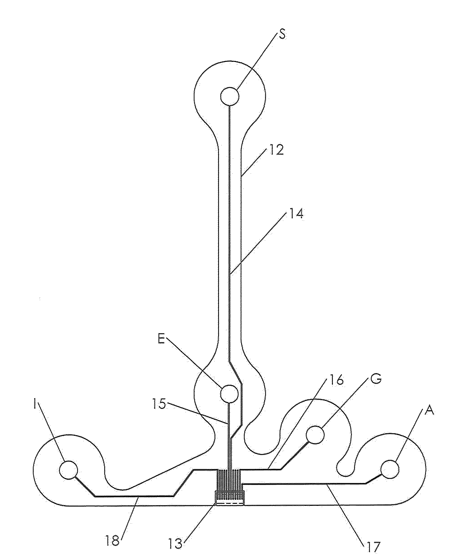
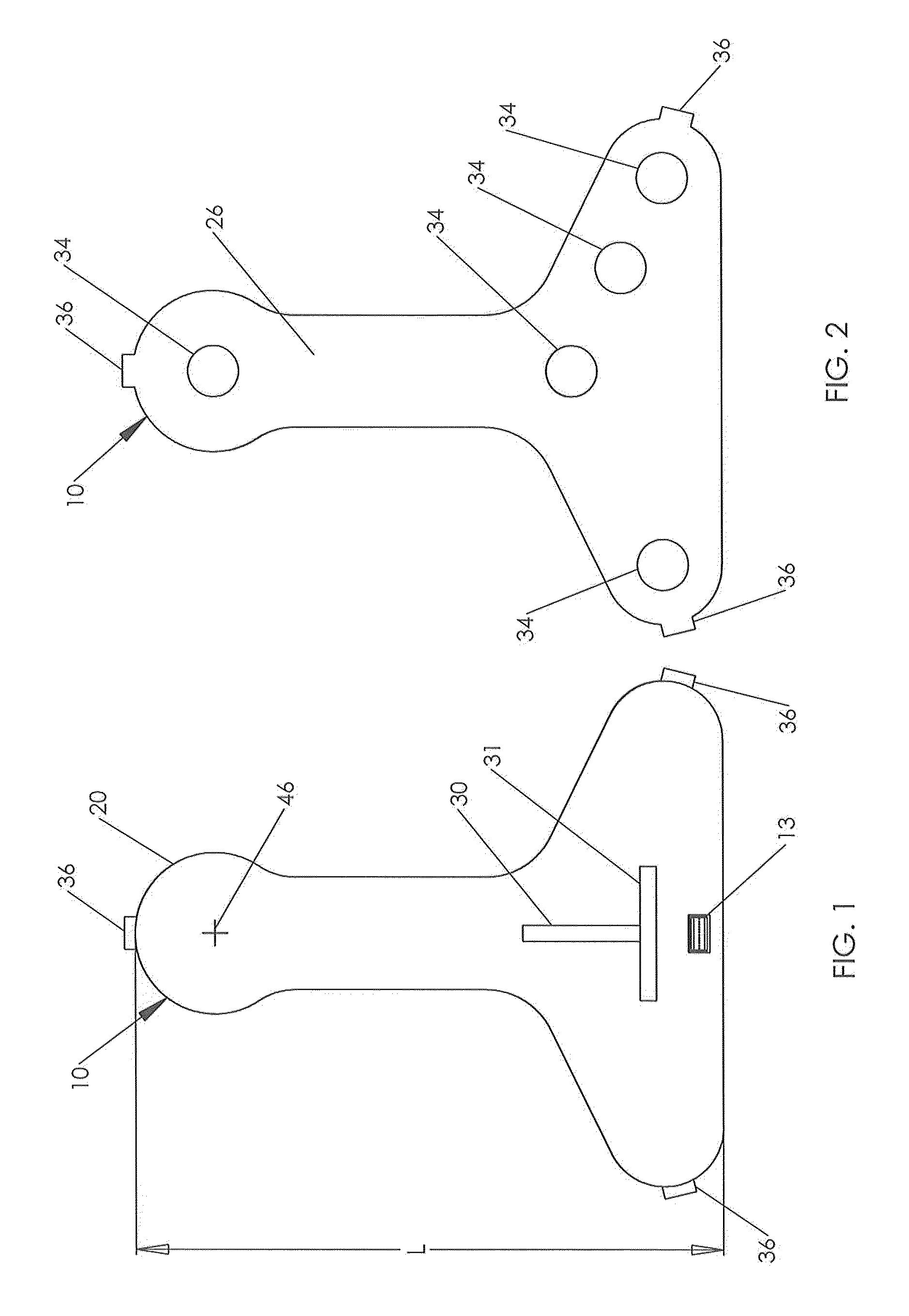
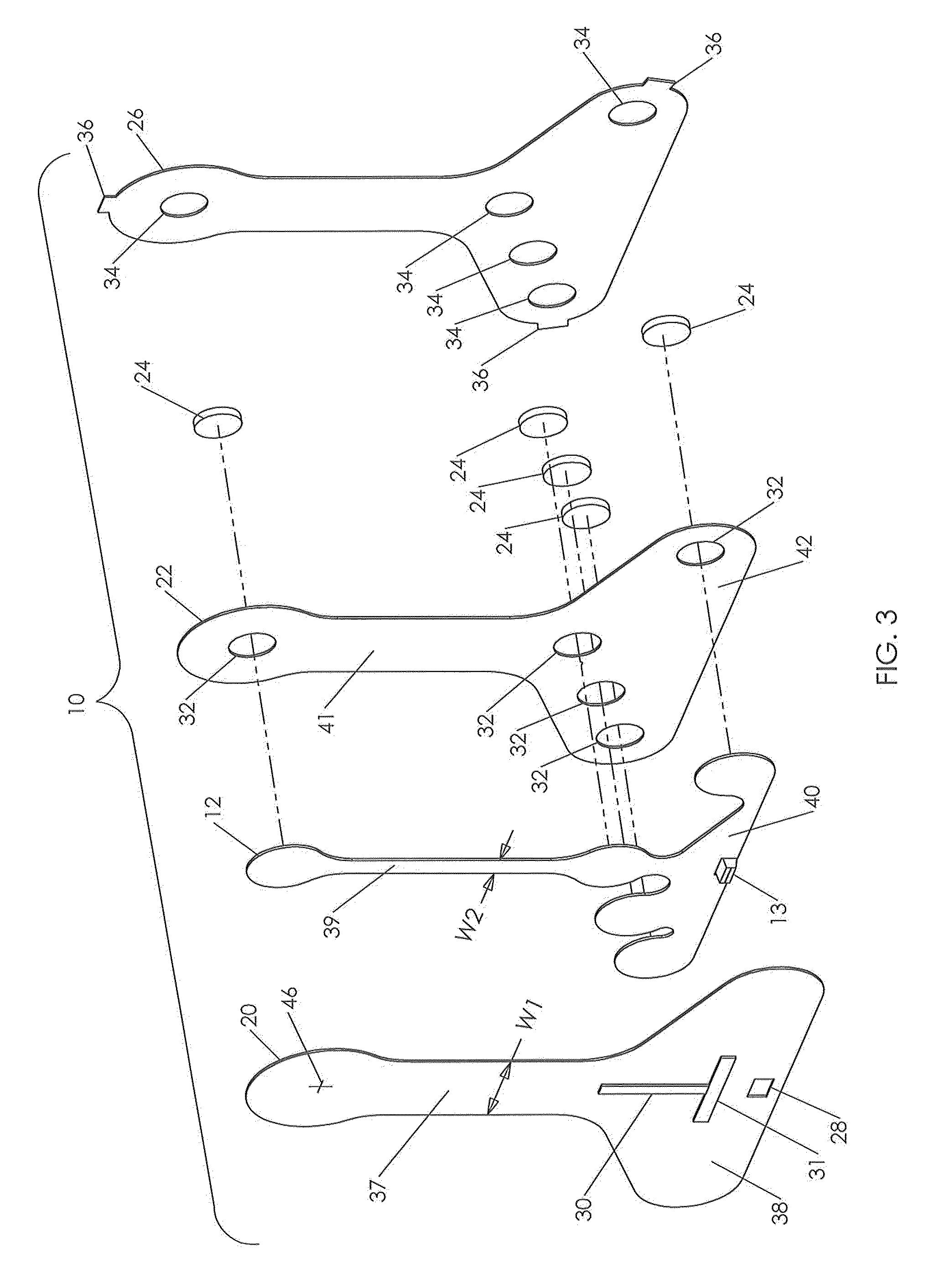
As shown in FIG. 4 the physiological sensor device or patch 10 of this first embodiment comprises a plurality of layers including: a flexible outer front layer 20; a flexible intermediate circuit layer 12 having a plurality of electrodes and electrical conductors fixed to a back side of this intermediate layer; a third flexible layer 22 that is the back layer having an adhesive on a back side of it for adhering the physiological sensor device or patch 10 to the chest of a patient; a plurality of conductive gel pads 24 adhered to the flexible intermediate circuit layer 12 with each gel pad aligned with and in conductive communication with one of the electrodes A, E, I, S and G and protruding through a portal 32 in the third flexible layer 22; and a rearmost layer 26 that is a liner releasable from an adhesive on the on the back side of the third flexible layer 22. It is understood that as used herein and in the claims the term “plurality” means two or more.

Preferably, the flexible ou...

Example

It is understood that features of the first embodiment and this second embodiment relating to the width of the flexible intermediate circuit layers 12, 52 and the presence or absence of a spare electrode SP may be employed in any combination desired without varying from the scope of the invention.

Another alternative embodiment of a physiological sensor device or patch 70 of the present invention is shown in FIGS. 7, 8, 9 and 10. FIG. 7 is a front view of this alternative embodiment; FIG. 8 is a rear view of this alternative embodiment; FIG. 9 is an exploded view of this alternative embodiment viewed from the front; and FIG. 10 is a rear view the flexible intermediate circuit layer 74 of this embodiment. This alternative embodiment is like the embodiment of FIGS. 5 and 6 with two notable distinctions, namely an additional horizontally extending portion 88 located at the top of the vertically extending portion 89 opposite the horizontally extending portion 90 at the lower end of the v...

Example

It is understood that the flexible intermediate circuit layer 74 of this third embodiment may if desired include a spare electrode like the spare electrode SP of the second embodiment located such that when the physiological sensor device or patch 70 is applied to the chest of a patient the spare electrode is located substantially midway along the length of the patient's sternum at an equal distance between electrodes E6 and E8. A conductor connects the spare electrode to the single common connector 13. As described above with respect to the second embodiment the spare electrode may be used to facilitate the collection of additional data from the patient such as an additional electrode to collect physiological data, temperature sensor, or change in resistance to measure breathing or chest compressions.

The third flexible layer 75 is substantially the same as the third flexible layers 22, 62 of the first and second embodiments described above, but it includes additional portals 32 to ...


PUM


Abstract

A physiological data collection system facilitates acquiring, recording, transferring and analyzing physiological signals generated from the skin of a human subject that may be used in generating an electrocardiogram for a patient in a continuous manner over an extended period of time of twenty four to forty eight hours. The physiological data collection system is an assembly of a disposable physiological sensor device and a reusable data collection module. Collected physiological data may be transmitted for analysis via either a cable or a wireless communication system.

Description

FIELD OF THE INVENTIONThe present invention relates to a device that is a system for collecting physiological data from a human subject in a continuous manner over an extended period of time of twenty four to forty eight hours. The physiological data collected by the system may be used in generating an electrocardiogram for the human subject.BACKGROUND OF THE INVENTIONThe ability to obtain electrical activity of the human heart from the surface of the skin that was effectuated by Augustus De'sire Waller in 1887 required the subject's limbs to be submersed in saline. In 1912 Willem Einthoven defined lead positions I, II and III which became known as Einthoven's Triangle. The use of physiological sensors or chest leads for the purpose of collecting electrical data generated by a person's heart in a clinical environment dates back to Charles Wolferth and Francis Wood in 1932. This led to the Wilson Central Terminal, an “indifferent electrode (neutral or grounding electrode)” by Frank W...

Claims


Application Information

Patent Timeline
IPC IPC(8): A61B5/0408
CPCA61B5/0006A61B5/04085A61B5/04325A61B5/1112A61N1/08A61B2560/0271A61B2560/0412A61B2560/0468A61B5/6833A61B5/282A61B5/335
Inventor MCGUSTY, EDWIN A.VOSCH, MICHAEL J.PARKER, III, JOHN W.
Owner HALTHION MEDICAL TECH INC
Why Eureka
Try Eureka