Spinal implant with flexible tie

US20110238118A1Active Publication Date: 2011-09-29ZIMMER SPINE SAS

Image

  • Spinal implant with flexible tie
  • Spinal implant with flexible tie
  • Spinal implant with flexible tie

Examples


Embodiment Construction

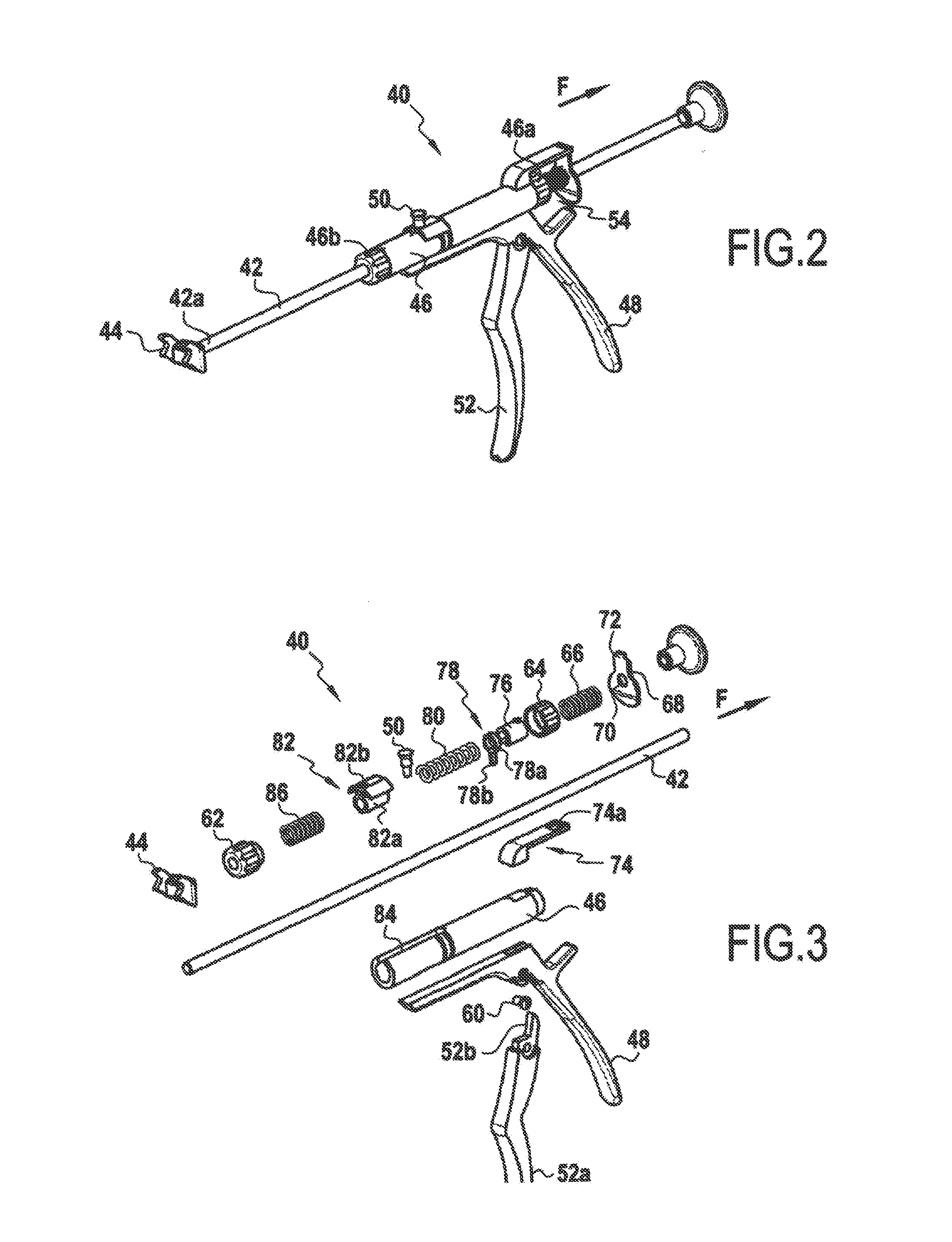
[0036]With reference initially to FIG. 2, there follows a description of the instrument assembly 40. It is essentially constituted by a rod 42 having a first end 42a fitted with bearing means 44 for bearing against the implant on which the tie is to be tensioned. The instrument 40 also has a moving part 46 that is movable in translation relative to the rod 42. The moving part 46 is generally cylindrical in shape and is provided with a handle 48. The moving part 46 also has a stud 50 on its portion remote from the handle 48. As explained below, the stud 50 serves to hold the tie on which tension is to be applied. The instrument 40 also comprises a control member constituted by a trigger 52. As explained below, actuating the trigger 52 serves to cause the moving part 46 to move rearwards relative to the rod 42 in the direction of arrow F. In addition, at its end 46a opposite from its end 46b closest to the bearing element 44, the moving part 46 is fitted with an anti-return system act...


PUM


Abstract

A spinal implant can be fastened on a bony element of a patient via a flexible tie. In some embodiments, the spinal implant has two jaws, each having a recess and an opening. The recess is configured to receive a portion of a rod. A portion of the flexible tie is passed through the opening and between a wall of the recess and a surface of the rod to form a loop that can be placed around the bony element. The two jaws are hinged at one end and engaged at the opposite end via a locking member. The locking member can be adjusted to simultaneously hold the jaws together in a fixed position relative to the rod and lock the flexible tie, which has been properly tensioned, in translation relative to the spinal implant.

Description

CROSS-REFERENCE TO RELATED APPLICATIONS[0001]This application is a continuation of and claims a benefit of priority under 35 U.S.C. §120 from U.S. patent application Ser. No. 12 / 408,592, filed Mar. 20, 2009, entitled “FLEXIBLE TIE FASTENING SYSTEM,” which is a continuation of and claims priority from U.S. patent application Ser. No. 11 / 996,918, filed Jan. 25, 2008, entitled “AN INSTRUMENT FOR TENSIONING A FLEXIBLE TIE,” which is the National Stage of International Application No. PCT / FR2006 / 050909, filed Sep. 20, 2006, which claims priority from French Patent Application No. 0509629, filed on Sep. 21, 2005. This application also relates to U.S. patent application Ser. No. ______, filed Jun. ______, 2011, entitled “METHOD AND INSTRUMENT FOR TENSIONING A FLEXIBLE TIE.” The content of each application referenced herein is hereby incorporated as if fully set forth herein.TECHNICAL FIELD OF THE INVENTION[0002]The invention relates to a spinal implant that can be fastened on a bony elemen...

Claims


Application Information

Patent Timeline
29 Sep 2011
Publication
US20110238118A1
IPC
A61B17/70; A61B17/88
CPC
A61B17/7053; A61B17/7062; A61B17/8869; A61B17/8861; A61B17/842
Inventors
BACCELLI, CHRISTIAN; LE COUEDIC, REGIS