Finite Difference Scheme for Solving Droplet Evaporation Lubrication Equations on a Time-Dependent Varying Domain

a lubrication equation and time-dependent technology, applied in the field offinite difference schemes, can solve problems such as film thickness, and achieve the effect of better approximation

Inactive Publication Date: 2011-09-29
KATEEVA
View PDF24 Cites 4 Cited by
  • Summary
  • Abstract
  • Description
  • Claims
  • Application Information

AI Technical Summary

Benefits of technology

[0009]Accordingly, embodiments of the present invention explicitly track the boundaries of the solute saturation regions over time. Only inside of this boundary are fluid and solute equations so

Problems solved by technology

The flow, though small, could introduce an error in simulation results in film thickness,

Method used


Image

  • Finite Difference Scheme for Solving Droplet Evaporation Lubrication Equations on a Time-Dependent Varying Domain
  • Finite Difference Scheme for Solving Droplet Evaporation Lubrication Equations on a Time-Dependent Varying Domain
  • Finite Difference Scheme for Solving Droplet Evaporation Lubrication Equations on a Time-Dependent Varying Domain

Examples


Embodiment Construction

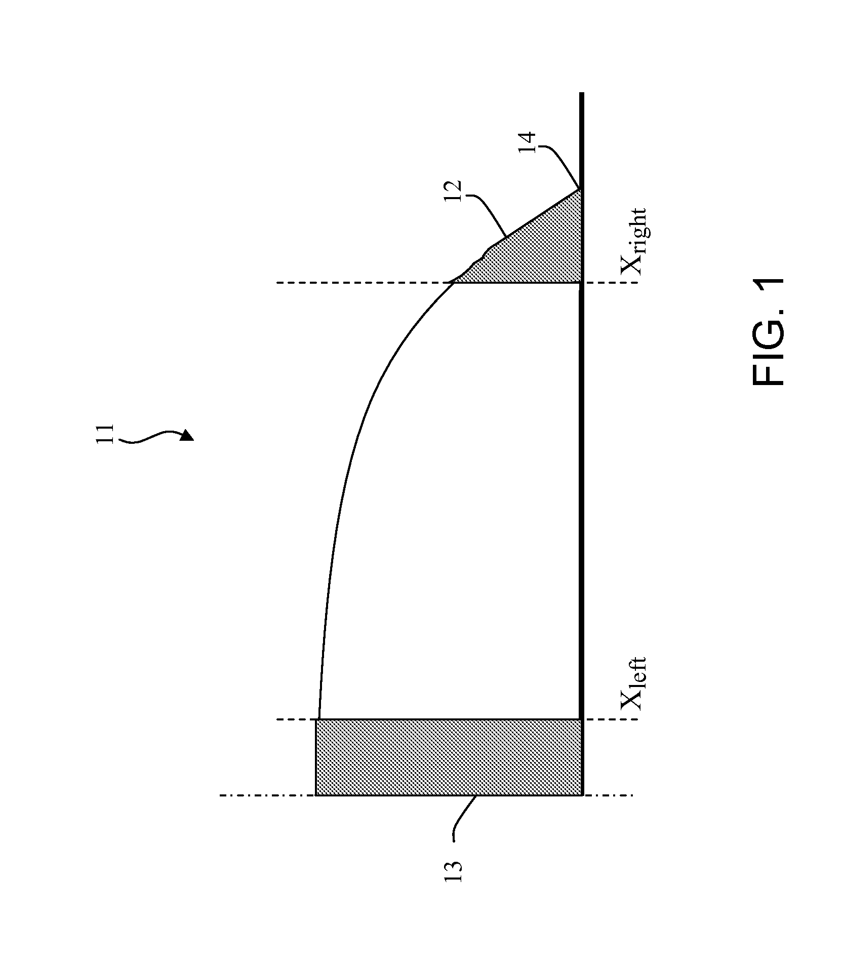
[0020]As previously noted, there is solute accumulation near the end points or contact lines of a droplet, and these regions, as well as a center region of the droplet, reach saturated concentration first. FIG. 1 schematically illustrates in cross-section half of a droplet 11 having an end region 12 and a center region 13. The internal boundary of end region 12 is denoted Xright, and an internal boundary of center region 13 is denoted Xleft. The outer boundary of end region 12 is a contact line 14, which is the interface between the fluid, substrate and air. It is to be understood that the other half of the droplet (not shown) would be symmetrical, and thus would include corresponding regions and boundaries. Xleft and Xright are each a function of time and determined by the concentration value to the left and right, respectively.

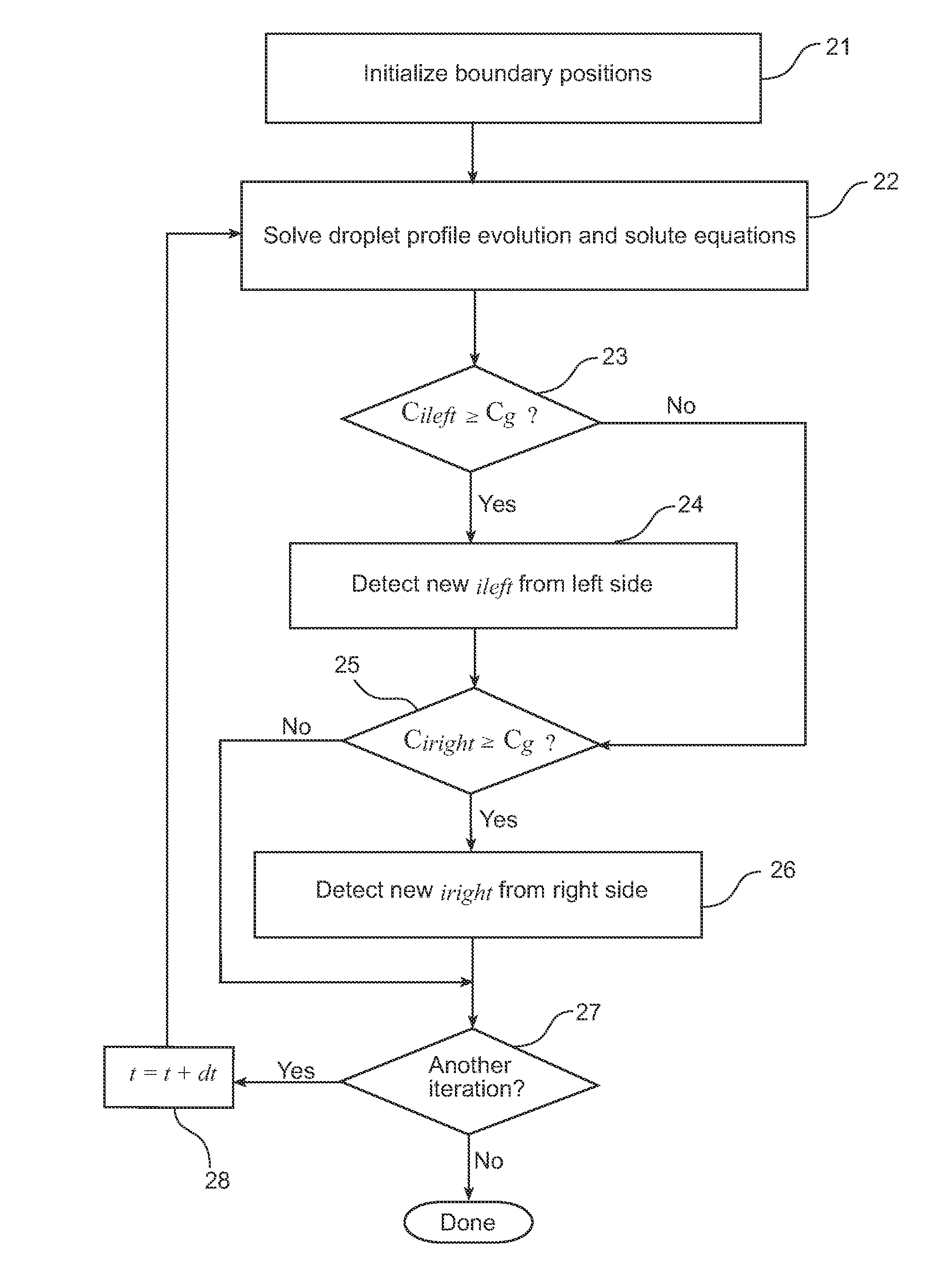
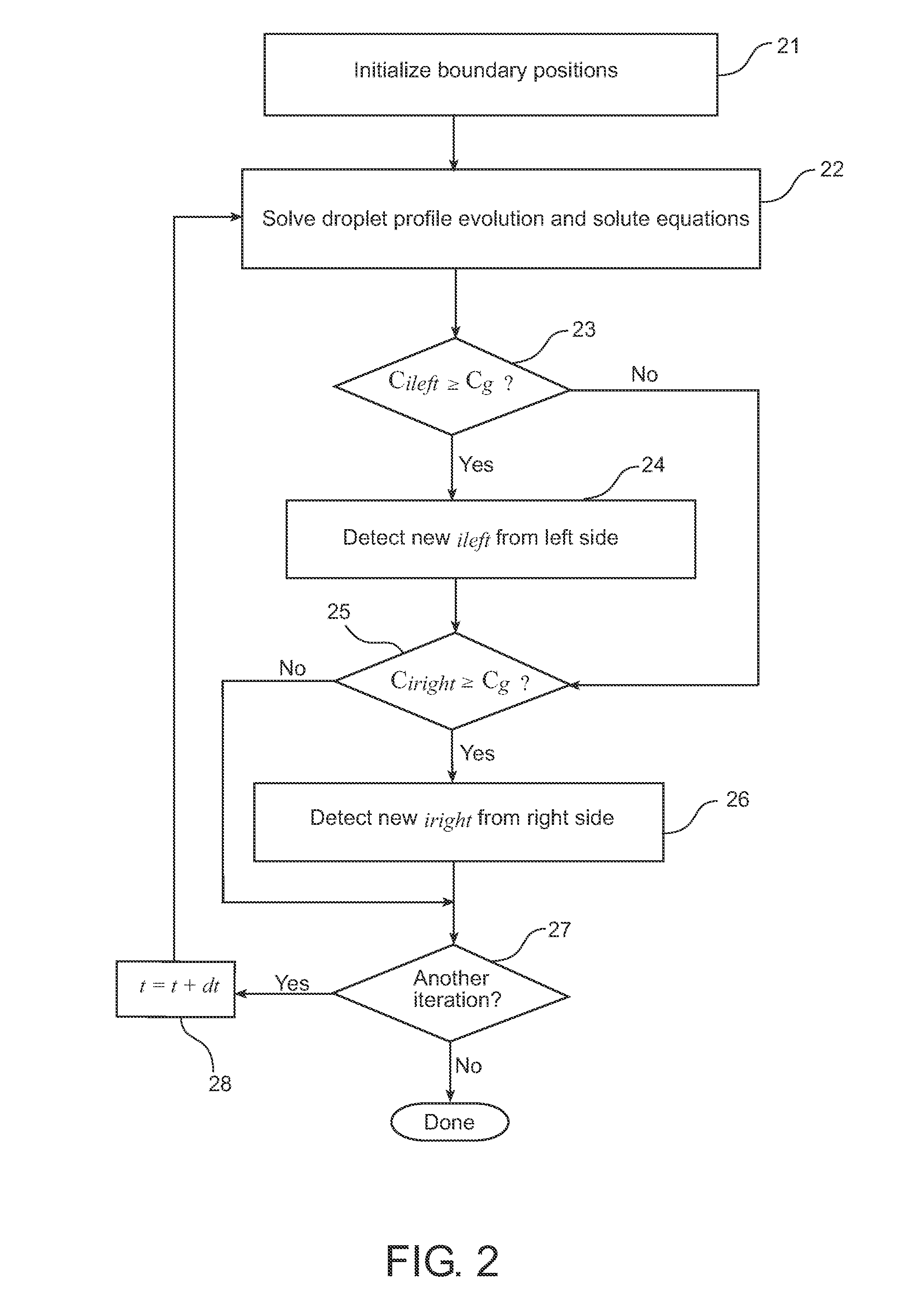
[0021]Referring now to FIG. 2, a finite-difference-based algorithm or method for simulating a droplet evaporation process on a domain whose size is varying ...


PUM


Abstract

The present invention is directed to simulating evaporation of a droplet of a fluid, and may be embodied in a system, method or a computer-readable medium encoded with instructions for a processor to carry out such simulation. The present invention solves equations, which may represent an approximation of evaporation of the droplet on a domain whose size is varying over time. The boundaries of saturation regions are tracked and updated over time, and the equations are iteratively solved with the new boundaries of the saturation regions.

Description

CROSS-REFERENCE TO RELATED APPLICATIONS[0001]The present application is related to following U.S. patent applications: U.S. patent application Ser. No. 12 / 476,588, filed on Jun. 2, 2009, entitled “A Finite Difference Algorithm for Solving Lubrication Equations with Solute Diffusion” (Attorney Docket No. AP357HO); and U.S. patent application Ser. No. 12 / 579,645, filed Oct. 15, 2009, entitled “An Upwind Algorithm for Solving Lubrication Equations” (Attorney Docket No. AP359HO). Each such related application is incorporated by reference herein in its entirety.BACKGROUND[0002]1. Field of Invention[0003]The present application is directed toward systems and methods for employing a finite difference scheme for simulating the evaporation of a droplet on a domain whose size is varying over time.[0004]2. Description of Related Art[0005]The industrial printing process includes the production of small ink droplets. Each ink droplet may contain one or more solvents and solutes. Such solute is a...

Claims


Application Information

Patent Timeline
IPC IPC(8): G06F17/11G06F17/13
CPCG06F17/13G06F2217/16G06F17/5018G06F2111/10G06F30/23
Inventor ZHANG, JIE
Owner KATEEVA
Why Eureka
Try Eureka