
Storage apparatus and data processing method for the same

a technology of storage apparatus and data processing method, which is applied in the direction of memory address/allocation/relocation, error detection/correction, instruments, etc., can solve the problems of increasing the amount of processing time required for data compression and decompression, increasing the amount of processing increasing the storage capacity of storage devices. , to achieve the effect of preventing the increase of processing time for redundancy determination, reducing the amount of processing time, and maximizing the storage capacity of storage devi

Active Publication Date: 2011-09-29
HITACHI LTD
View PDF7 Cites 19 Cited by
  • Summary
  • Abstract
  • Description
  • Claims
  • Application Information

AI Technical Summary

Benefits of technology

[0015]This invention enables the storage system to utilize the storage capacity of the storage device effectively, and at the same time, to prevent the amount of processing time required for data compression and decompression from increasing. In addition, while the storage system executes the high-precision redundancy determination for the transfer information from the higher-level device and the storage information stored in the storage device, the amount of processing time for redundancy determination can be prevented from increasing by improving the operation efficiency for that operation.

Problems solved by technology

However, as there are more segments, the capacity of the hash mean management table increases significantly, and it takes more time to detect redundancy between transfer information and stored information.
In such algorithms the number of operations is large and processing latency increases.
In light of this, there has been a problem whereby, in the high-precision detection of redundancy in storage systems, the processing time increases and the I / O performance of the storage system with respect to higher-level computers deteriorates.
Furthermore, if storage systems attempt to compress a large quantity of data and store all of it in a storage device, the storage device eventually fails to be effectively utilized, and in addition, it takes time to compress and decompress the data.

Method used


Image

  • Storage apparatus and data processing method for the same
  • Storage apparatus and data processing method for the same
  • Storage apparatus and data processing method for the same

Examples


Embodiment Construction

[0043]This section describes an embodiment of this invention using the figures. Note that the invention is not limited to the embodiments described below.

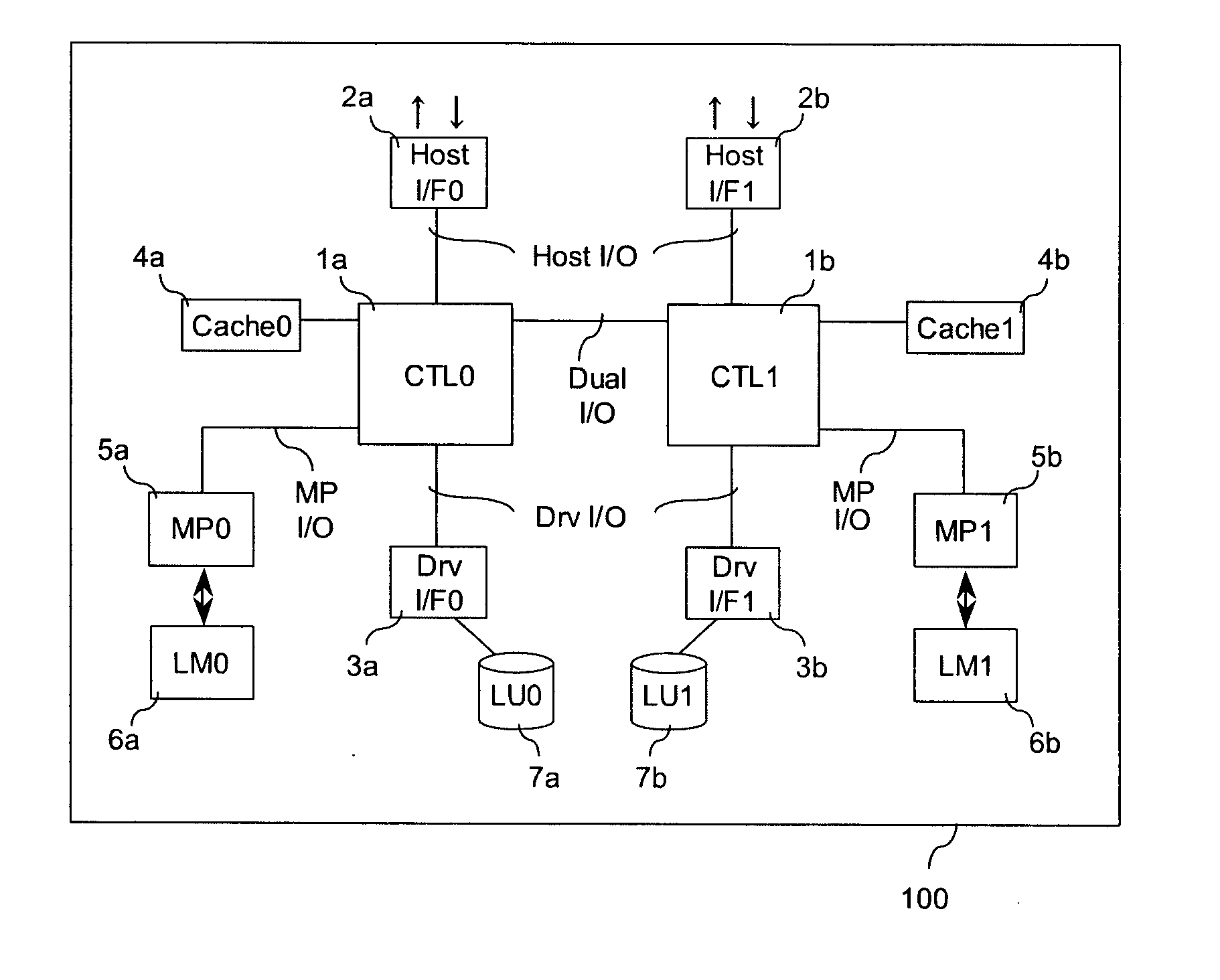
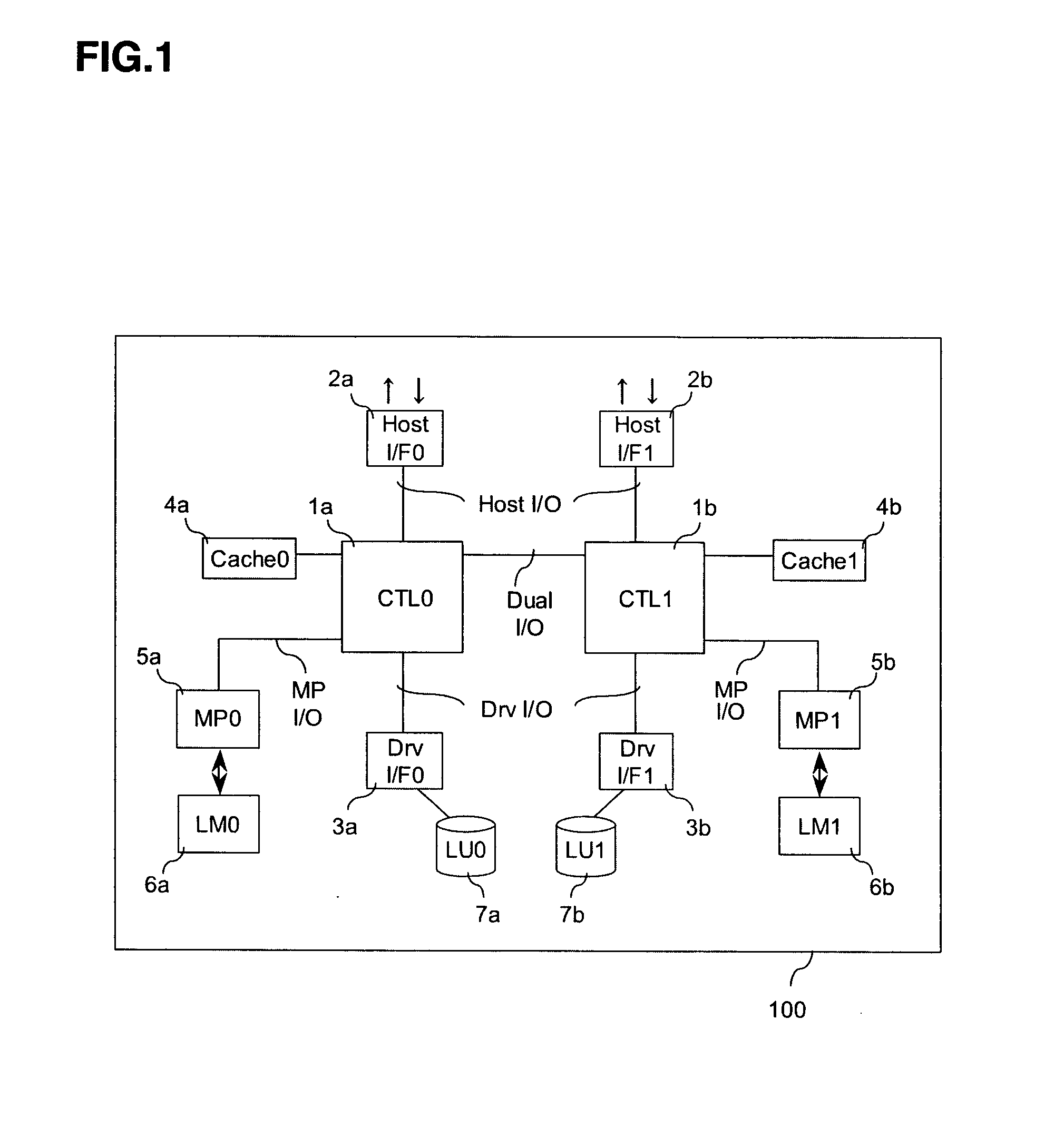
[0044]FIG. 1 is a block diagram showing the configuration of the storage system 100 related to this invention. FIG. 1 is a block diagram showing a configuration example of the storage system 100. The storage system has a first controller (CTL1: 1a) and a second controller (CTL0: 1b) that are redundant. The two controllers are connected by Dual I / O.

[0045]To each of the controllers, devices including a cache memory (Cache0: 4a or Cache1: 4b), a host interface (Host I / F0: 2a or Host I / F1: 2b), a drive interface (Dry I / F0: 3a or Dry I / F1: 3b), and a microprocessor (MP0: 5a or MP1: 5b) are connected. Each of the controllers controls information and data transfer via I / O (information and data transfer paths) among multiple devices.

[0046]The host interfaces 2a and 2b are the interfaces that control information transfer with the higher-lev...


PUM


Abstract

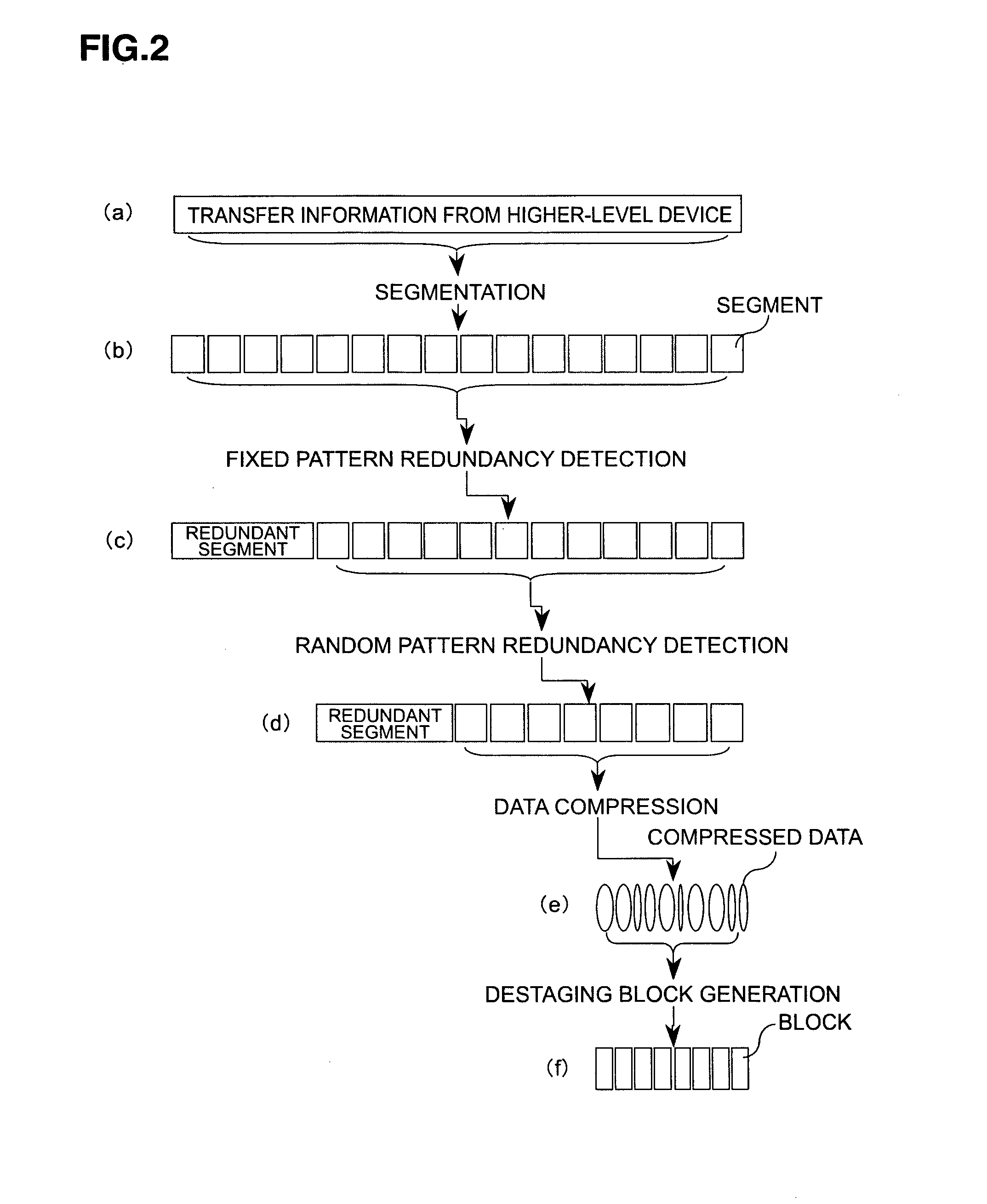
The present invention aims for efficient use of storage capacity in a storage system by reducing the amount of time taken for processing including removing redundancy and data compression executed with respect to transferred data.Focusing on data patterns included in transferred data, the most suitable pattern is detected, and de-duplication processing is gradually executed. Data compression is then executed with data after de-duplication as a target. Determination of the decision for execution of gradual de-duplication processing, or execution of compression processing is made depending on the amount of data remaining at each processing stage and the system load.

Description

TECHNICAL FIELD[0001]This invention relates to a storage system and a data processing method in the storage system.BACKGROUND ART[0002]Conventionally, storage systems have stored transfer information transferred from a higher-level device (host) temporarily in cache memory, and then stored it in a storage device such as a hard disk. Recently, a technology has been proposed in which a storage system detects redundancy between transfer information and information already stored in a storage system, and transfer information determined as being redundant is not stored in a storage device. By preventing the storage system from storing such “redundant information” in the storage device, the physical storage capacity can be utilized effectively, and as a result the apparent storage capacity that the storage system shows to the host can be increased.[0003]An example of such redundancy detection is described in U.S. Pat. No. 6,928,526. The storage system processes transfer information in uni...

Claims


Application Information

Patent Timeline
Patent Type & Authority Applications(United States)
IPC IPC(8): G06F12/08
CPCH03M7/30G06F11/1451
Inventor HIRAYAMA, HIROSHI
Owner HITACHI LTD
Learn More