Storage device

a storage device and a technology for liquid/fluent solids, applied in the direction of sustainable buildings, liquid/fluent solid measurements, instruments, etc., can solve the problem of non-working storage without, and achieve the effect of preventing an increase in power consumption

Inactive Publication Date: 2011-09-29
BUFFALO CORP LTD
View PDF11 Cites 42 Cited by
  • Summary
  • Abstract
  • Description
  • Claims
  • Application Information

AI Technical Summary

Benefits of technology

[0013]In a preferable aspect, the first power supply capacity is higher than the second power supply capacity, and when the identified type of the interface is the first interface, the control unit increases the number of simultaneous accesses to be greater than a number of simultaneous accesses in connection with the second interface.
[0014]The storage device of this aspect increases the number of simultaneous accesses to the plurality of the storage units for the interface having the higher power supply capacity. This feature enhances the data reading speed or the data writing speed.
[0016]In the storage device of this aspect, the control unit reads or writes data from or into the plurality of the storage units in an identical sequence, whether the connected interface is the first interface or the second interface. In the state that some data have already been distributed and written into the plurality of the storage units, even when the connected interface is changed, this feature enables data to be normally written into or read from the plurality of the storage units without requiring any special processing, such as special address conversion.
[0018]The storage device of this aspect causes a non-working storage with no data currently written into or read from to be standby. In connection with the interface having the less number of simultaneous accesses, this feature especially effectively reduces the power consumption.
[0024]In connection with the interface having the lower power supply capacity, the storage device of this aspect effectively prevents an increase of the power consumption during analysis of the protocol.

Problems solved by technology

This issue is not characteristic of the SSD but is commonly found in devices connectable with multiple different interfaces having different power supply capacities.
The storage device of this aspect causes a non-working storage with no data currently written into or read from to be standby.

Method used


Image

  • Storage device
  • Storage device
  • Storage device

Examples


first embodiment

A. First Embodiment

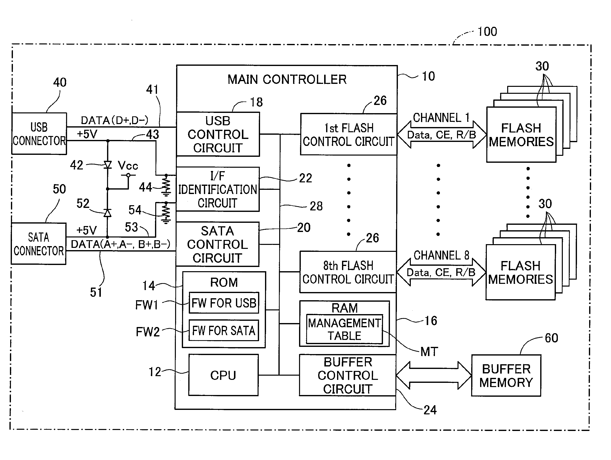
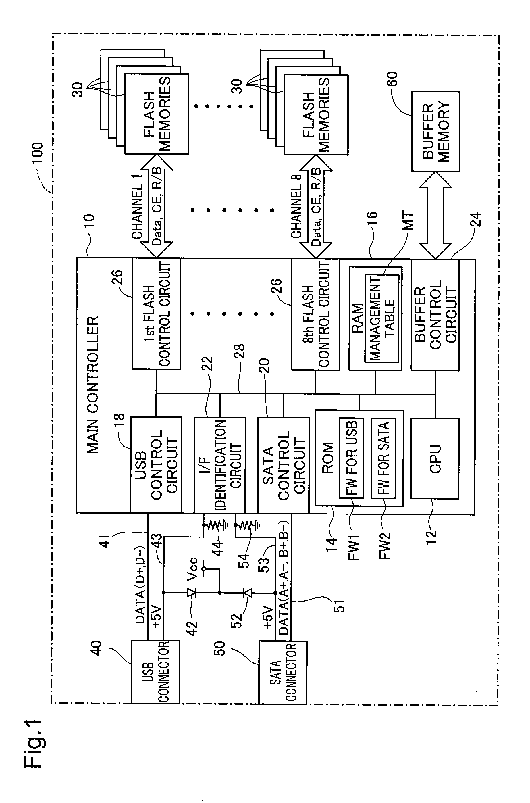
[0038]FIG. 1 is an illustration depicting the configuration of an SSD according to a first embodiment of the invention. The SSD 100 of this embodiment is configured as a secondary storage device used in connection with a host device (not shown), such as a personal computer. The SSD 100 includes a main controller 10, multiple flash memories 30, a USB connector 40, an SATA connector 50, and a buffer memory 60.

[0039]The main controller 10 includes a CPU 12, a ROM 14, a RAM 16, a USB control circuit 18, an SATA control circuit 20, an interface identification circuit 22, and a buffer control circuit 24, as well as eight flash control circuit 26 (1st to 8th flash control circuits). These components are interconnected via an internal bus 28.

[0040]The USB connector 40 is connected to the USB control circuit 18 via one set of data signal lines 41 (D+ and D−). The USB control circuit 18 controls data input and output in conformity with a USB 2.0 standard from and to a host ...

second embodiment

B. Second Embodiment

[0062]FIG. 9 is an illustration depicting the configuration of an SSD according to a second embodiment of the invention. The like components in the SSD 100b of the second embodiment shown in FIG. 9 to those in the SSD 100 of the first embodiment shown in FIG. 1 are expressed by the like numerals and symbols. The primary difference of the SSD 100b of the second embodiment shown in FIG. 9 from the SSD 100 of the first embodiment shown in FIG. 1 is omission of the SATA connector 50, the SATA control circuit 20, the interface identification circuit 22, and the firmware FW2 for SATA.

[0063]The SSD 100b of this embodiment has a USB connector 40b in conformity with a USB 3.0 standard. The USB 3.0 uses two sets of data signal lines 41b and enables data input and output from and to a host device at a communication speed of up to 5.0 Gbps. The USB 3.0 has power supply of up to 5V and 900 mA, which is almost twice the power supply amount in the USB 2.0 standard. The USB 3.0 ...

modification 1

[0069]FIG. 11 is an illustration depicting the configuration of an SSD in a first modification. The SSD 100c of this modification has a different configuration of connection between the SATA connector 50 and the main controller 10 from the configuration in the SSD 100 of the first embodiment shown in FIG. 1. In the configuration of the first embodiment, both the power line 43 of the USB connector 40 and the power line 53 of the SATA connector 50 are connected to the interface identification circuit 22. In the configuration of this modification, only the power line 43 of the USB connector 40 is connected to the interface identification circuit 22. In this modified configuration, in the case of no power supply via the USB connector 40, the interface identification circuit 22 identifies the power supply via the SATA connector 50. The SSD 100c of this modification can thus identify the connection interface like the SSD 100 of the first embodiment. In a generalized configuration adopting...


PUM


Abstract

The storage device comprises a storage unit configured to store data in a non-volatile manner; a first connector configured to be connectable with a first interface having a first power supply capacity and receive a supply of electric power for operating the storage device from the first interface; a second connector configured to be connectable with a second interface having a second power supply capacity and receive a supply of electric power for operating the storage device from the second interface; an identification unit configured to identify a type of an interface connected via the first connector or the second connector; and a control unit configured to control power consumption of the storage unit according to the identified type of the interface.

Description

CROSS-REFERENCE TO RELATED APPLICATION[0001]The present application claims the priority based on Japanese Patent Application No. 2010-72767 filed on Mar. 26, 2010, the disclosure of which is hereby incorporated by reference in its entirety.BACKGROUND[0002]1. Technical Field[0003]The present invention relates to a storage device for non-volatile storage of data transferred from, for example, a computer.[0004]2. Related Art[0005]Memory cards with internal flash memories have been used in various applications as storage devices connected to a computer (see, for example, JP 2008-33379). A storage device with high-capacity flash memories called an SSD (solid state drive) has recently been used often, in place of a conventional hard disk drive. The SSD is generally connected to the computer by means of an interface, for example, USB (Universal Serial Bus), SATA (Serial ATA), or PATA (Parallel ATA). Some of SSDs are equipped with multiple different types of interfaces.[0006]Among these dif...

Claims


Application Information

Patent Timeline
Patent Type & Authority Applications(United States)
IPC IPC(8): G06F1/26
CPCG06F3/0625G06F3/0688G06F13/385Y02B60/1246Y02B60/1228Y02B60/1235G11C16/102Y02D10/00
Inventor NODA, TAKAHIRO
Owner BUFFALO CORP LTD
Why Eureka
Try Eureka