Building-integrated photovoltaic power unit

a photovoltaic power unit and integrated technology, applied in the direction of pv power plants, heat collector mounting/support, light and heating equipment, etc., can solve the problems of low work efficiency at a construction site, degraded waterproof performance, and long time, so as to increase the strength/rigidity of the solar cell module, increase the durability and reliability, and increase the strength/rigidity

Inactive Publication Date: 2011-10-06
YANEGIJUTSUKENKYUJO CO LTD
View PDF10 Cites 38 Cited by
  • Summary
  • Abstract
  • Description
  • Claims
  • Application Information

AI Technical Summary

Benefits of technology

[0031]According to the present invention, a sheathing roof board is used as the functional member in the solar cell module and therefore, the strength/rigidity of the solar cell module can be increased and durability and reliability can be increased by increasing the strength/rigidity of the whole building-integrated photovoltaic power unit. Since the sheathing roof board is integrated into the solar cell module, the sheathin

Problems solved by technology

When solar cell modules are installed/constructed on the roof, there is a problem that working efficiency at a construction site is low and thus, it takes a long time because solar cell modules are arranged and installed after solar cell modules and bases or the like to install solar cell modules being carried onto the inclined roof.
However, according to JP-A No. 2002-061355, after solar panels being inserted into lattices of a skeleton member together with a heat insulator such as Styrofoam, the solar panels are prevented from slipping out of the lattices only by a pressing member fixed on the upper surface of the skeleton member and thus, there is a problem that waterproof performance is degraded

Method used


Image

  • Building-integrated photovoltaic power unit
  • Building-integrated photovoltaic power unit
  • Building-integrated photovoltaic power unit

Examples


Embodiment Construction

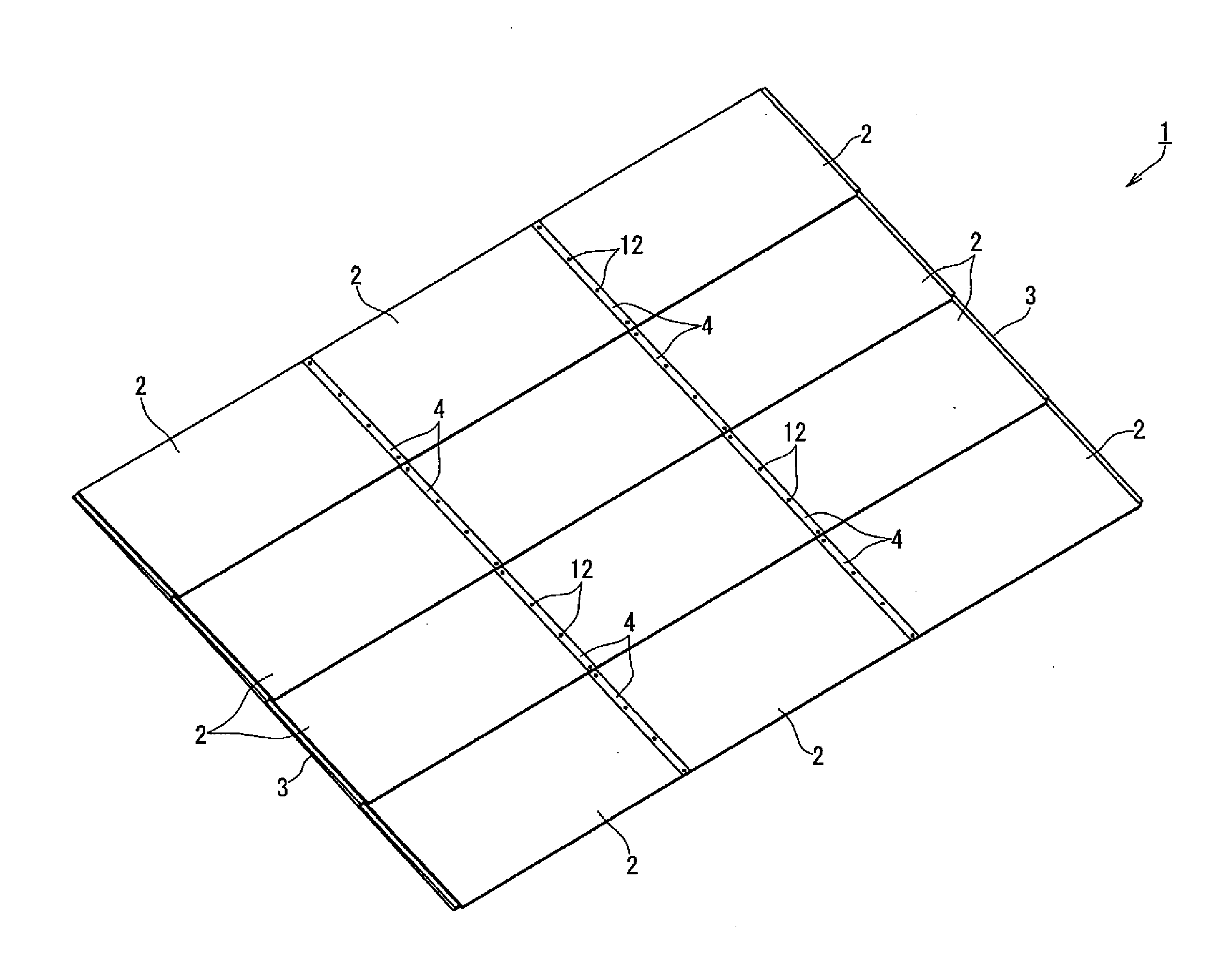
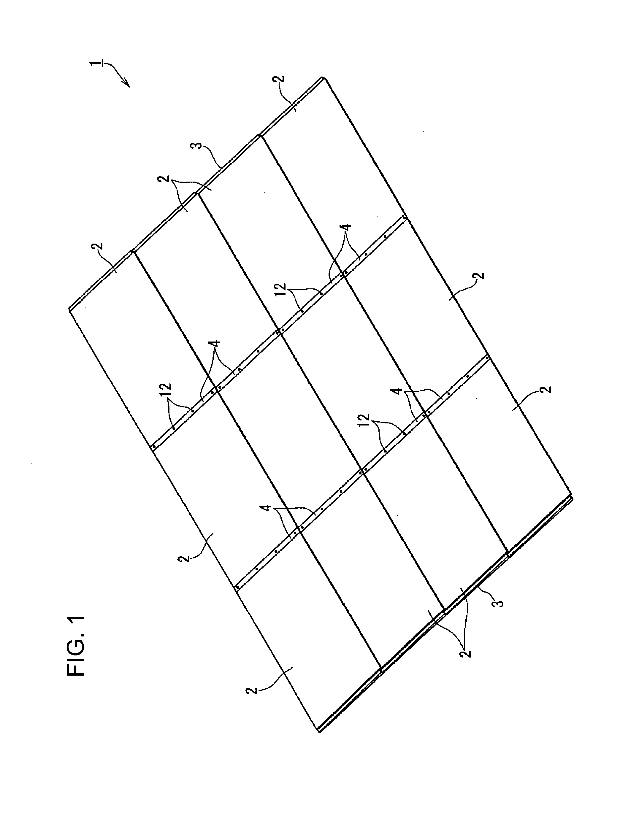
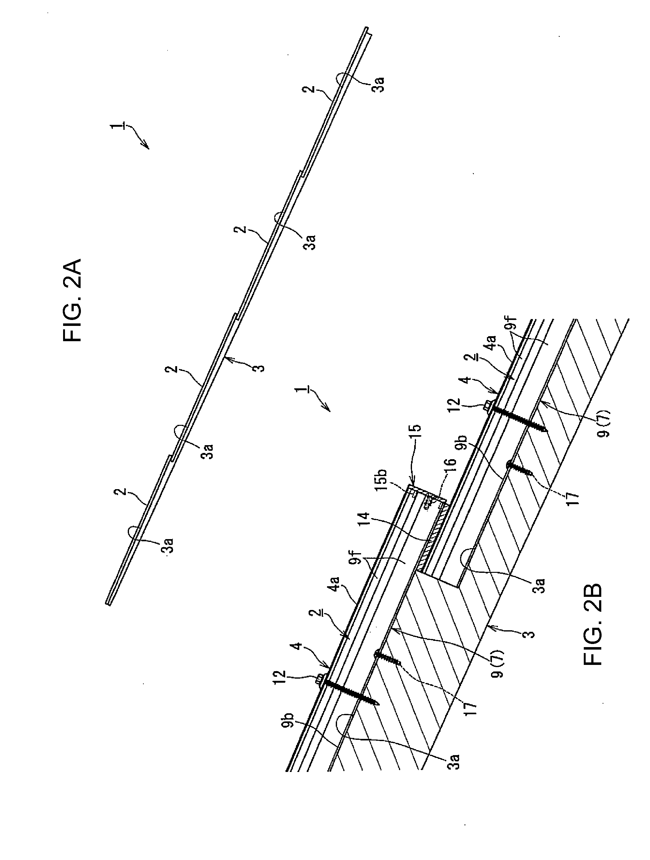
[0043]A building-integrated photovoltaic power unit that is a preferred embodiment of the present invention will be described below in detail with reference to FIGS. 1 to 6. FIG. 1 is a perspective view showing a whole building-integrated photovoltaic power unit of the present invention. FIG. 2A is a side view of the building-integrated photovoltaic power unit of the present invention and FIG. 2B is a side sectional view showing a side section by enlarging the side section. FIG. 3 is a sectional view of the building-integrated photovoltaic power unit of the present invention by cutting the unit in a horizontal direction and FIG. 4 is a diagram showing an eaves-side tip of the building-integrated photovoltaic power unit of the present invention by enlarging the eaves-side tip. FIG. 5 is a perspective view showing a tip cap in the building-integrated photovoltaic power unit of the present invention and FIG. 6 is an exploded view showing by breaking down FIG. 3. Further, FIG. 7 is an e...


PUM


Abstract

A building-integrated photovoltaic power unit comprising: a solar cell module including a solar panel, a functional member, and a frame body including a first frame formed with an installation part extending outward and holding the functional member and the opposing edges of the solar panel facing each other; a processed rafter including a supporting member, the processed rafters including processed rafters configured as a structure of a roof, each having a width to allow installation parts of different solar cell modules facing each other to be installed thereon in a state where supporting members are successively installed stepwise in a longitudinal direction; and a cap member fixed to the processed rafter including a ceiling part covering upper surfaces of the first frames of the solar cell modules installed such that the respective installation parts face each other on an upper surface of the processed rafter.

Description

BACKGROUND OF THE INVENTION[0001]1. Field of the Invention[0002]The present invention relates to a building-integrated photovoltaic power unit capable of constituting a roof of a building or the like.[0003]2. Description of the Related Art[0004]Photovoltaic power generation by installing roofing tiles equipped with solar cells or solar cell modules obtained by enclosing plate-shaped solar panels with a frame on the roof of a building or the like has been known. When solar cell modules are installed / constructed on the roof, there is a problem that working efficiency at a construction site is low and thus, it takes a long time because solar cell modules are arranged and installed after solar cell modules and bases or the like to install solar cell modules being carried onto the inclined roof.[0005]Thus, a proposal is made to insert solar panels into lattices of a skeleton member formed like a grid by horizontal muntins and vertical muntins as a structure of a roof in a plant in advanc...

Claims


Application Information

Patent Timeline
IPC IPC(8): E04D13/18
CPCF24J2/045F24J2/5211F24J2002/0061F24J2002/5296H02S20/23Y02B10/20Y02E10/44Y02E10/47Y02B10/12F24S20/67F24S25/20F24S2020/13F24S2025/022Y02B10/10Y02E10/50Y02A30/60
Inventor TSUZUKI, JOJIKOBAYASHI, SHUICHIYAMAUCHI, KENJI
Owner YANEGIJUTSUKENKYUJO CO LTD
Why Eureka
Try Eureka