Device for generating and transmitting heat capable of operating with fuel in any physical state and combustion flame

a technology of generating and transmitting heat and a combustion flame, which is applied in the direction of combustion process, lighting and heating apparatus, combustion types, etc., can solve the problems of inability to use any solution described in the patent to use liquid or gas fuel, breakage, etc., and achieve significant fuel savings, reduce pollution emissions, and maximize combustion efficiency

Inactive Publication Date: 2011-10-06
NUNEZ SUAREZ RENE MAURICIO
View PDF11 Cites 0 Cited by
  • Summary
  • Abstract
  • Description
  • Claims
  • Application Information

AI Technical Summary

Benefits of technology

[0002]The present invention, as the present specification states in its title, is intended to provide a device for generating and transmitting heat capable of operating with fuel in any physical state, i.e. it can be fed with fuel in solid, liquid or gas state. In turn, it is an object of the invention to maximize the combustion efficiency, i.e. that the fuel consumption is intended to be optimized, which results in significant fuel savings and the reduction of the emissions of pollutants.
[0003]Likewise, the present invention is intended to describe a combustion flame generated inside the described device for generating and transmitting heat, flame whose properties are highly advantageous in terms of heat transfer and for preventing the production of pollutants.

Problems solved by technology

Although said document explicitly states that the described apparatus can be used “for other types of fuels such as powder fuels, liquid fuels or gas fuels”, the practice shows that it is not possible to use any of the solutions described in said patent with liquid or gas fuels.
Additionally, the device for generating heat described in U.S. Pat. No. 6,651,645-B1 has some drawbacks, such as the fact that due to the high temperatures reached inside the combustion chamber, the substantially parallel plates or discs wherein the air injectors are embedded, are bent; which can lead to their breakage.

Method used


Image

  • Device for generating and transmitting heat capable of operating with fuel in any physical state and combustion flame
  • Device for generating and transmitting heat capable of operating with fuel in any physical state and combustion flame
  • Device for generating and transmitting heat capable of operating with fuel in any physical state and combustion flame

Examples


Embodiment Construction

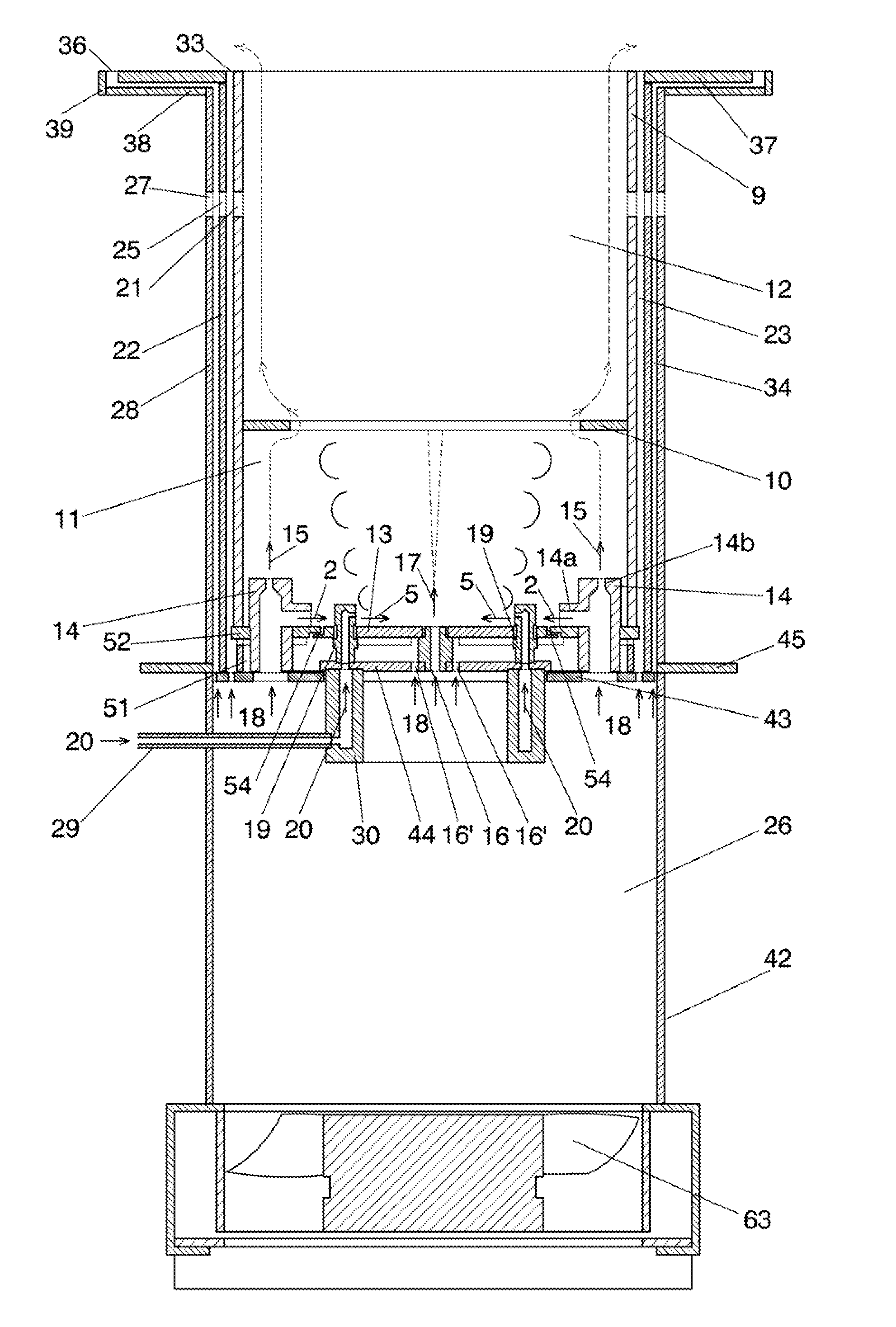
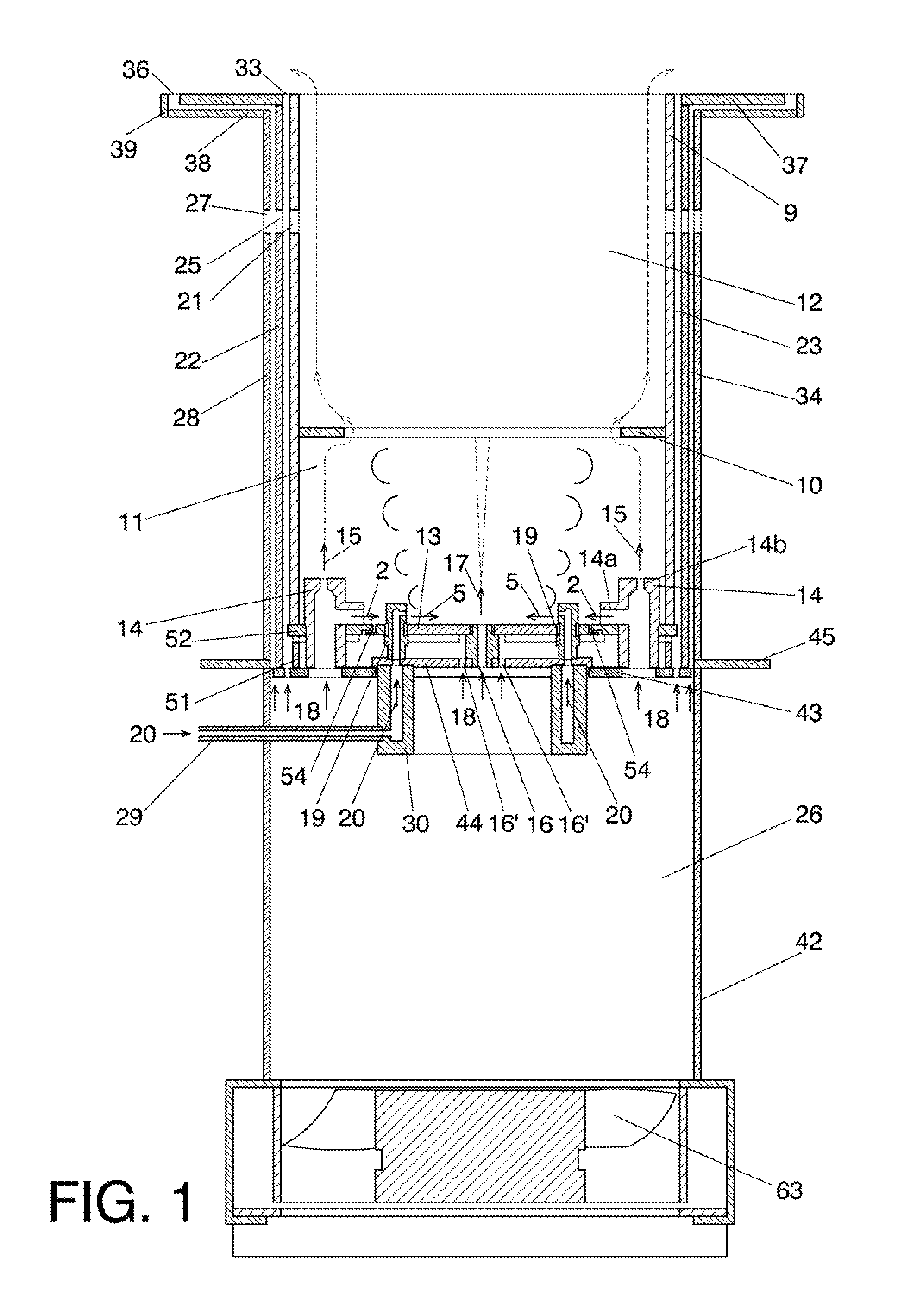
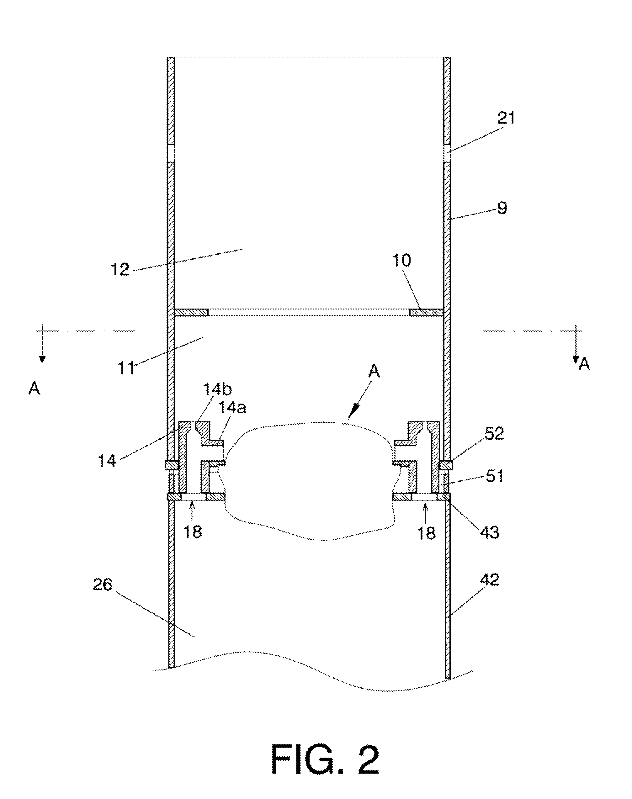
[0016]The present invention is intended to provide a device for generating and transmitting heat, capable of operating with fuel in any physical state, i.e. fuel in solid, liquid or gas state, which in turn allows to achieve the desired objectives and overcome the drawbacks of heat generators existing in the prior art.

[0017]Thus, the new device for generating and transmitting heat, object of the present invention comprises at least one combustion chamber preferably with a tubular shape, preferably constituted by a cylinder. Said cylinder is preferably divided into two sections, a lower section and an upper section of variable height. The height may be varied depending on the density of heat per volume unit of the combustion flame to be obtained in the combustion chamber. Furthermore, the apparatus of the present invention comprises a pressurized air chamber disposed below the lower section of the cylinder that forms the combustion chamber, and a plurality of air injectors.

[0018]The ...


PUM


Abstract

Device for generating and transmitting heat capable of operating with fuel in any physical state that includes at least one cylindrical combustion chamber (9) divided into a lower section (11) and an upper section (12) of variable height, a pressurized air chamber (26) arranged below the lower section (11) of the combustion chamber, and a plurality of air injectors (14). The device is characterized in that the air injectors (14) are supported on a flat ring (43) and set in a second flat ring (52) and in that it also includes a set of replaceable parts (A) arranged in the free centre of both flat rings (43 and 52) and whose specific configuration depends on the physical state of the fuel being used. Furthermore said set of replaceable parts (A) includes at least one central air injector (16) located in the geometric centre of the unit.

Description

[0001]This application is a continuation application of International Application PCT / SV2008 / 000003, filed Oct. 9, 2008, the disclosure of which is herein incorporated by reference in its entirety.OBJECT OF THE INVENTION[0002]The present invention, as the present specification states in its title, is intended to provide a device for generating and transmitting heat capable of operating with fuel in any physical state, i.e. it can be fed with fuel in solid, liquid or gas state. In turn, it is an object of the invention to maximize the combustion efficiency, i.e. that the fuel consumption is intended to be optimized, which results in significant fuel savings and the reduction of the emissions of pollutants.[0003]Likewise, the present invention is intended to describe a combustion flame generated inside the described device for generating and transmitting heat, flame whose properties are highly advantageous in terms of heat transfer and for preventing the production of pollutants.TECHN...

Claims


Application Information

Patent Timeline
Patent Type & Authority Applications(United States)
IPC IPC(8): F23L1/00F23C1/00F23H3/00F23K5/00
CPCF23C1/00F23D11/404F23D14/20F23M9/06F23L1/00F23L9/02F23M3/14F23D17/00
Inventor NUNEZ SUAREZ, RENE MAURICIO
Owner NUNEZ SUAREZ RENE MAURICIO
Why Eureka
Try Eureka