Evaporative emissions system with canister having improved venting structure, and vehicle including same

a technology of evaporative emissions and canisters, which is applied in the field of vehicles, can solve the problems of additional structure required for fixing or layout of vent pipes, and the possibility of water entering the canister, and achieve the effects of suppressing water entry, suppressing water entry, and suppressing water entry

a technology of evaporative emissions and canisters, which is applied in the field of vehicles, can solve the problems of additional structure required for fixing or layout of vent pipes, and the possibility of water entering the canister, and achieve the effects of suppressing water entry, suppressing water entry, and suppressing water entry

US20110239994A1Inactive Publication Date: 2011-10-06HONDA MOTOR CO LTD

Image

  • Evaporative emissions system with canister having improved venting structure, and vehicle including same
  • Evaporative emissions system with canister having improved venting structure, and vehicle including same
  • Evaporative emissions system with canister having improved venting structure, and vehicle including same

Examples


Embodiment Construction

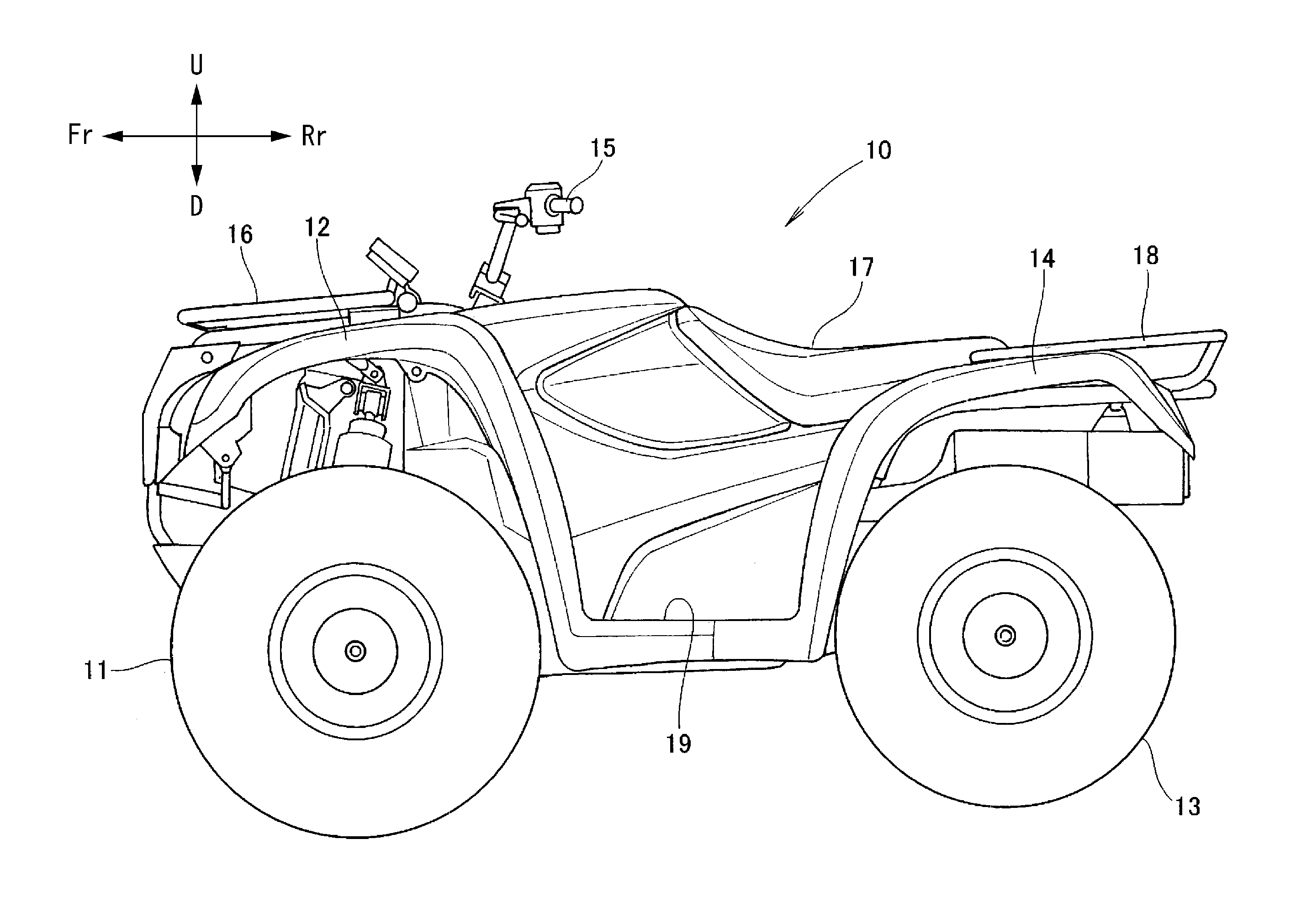
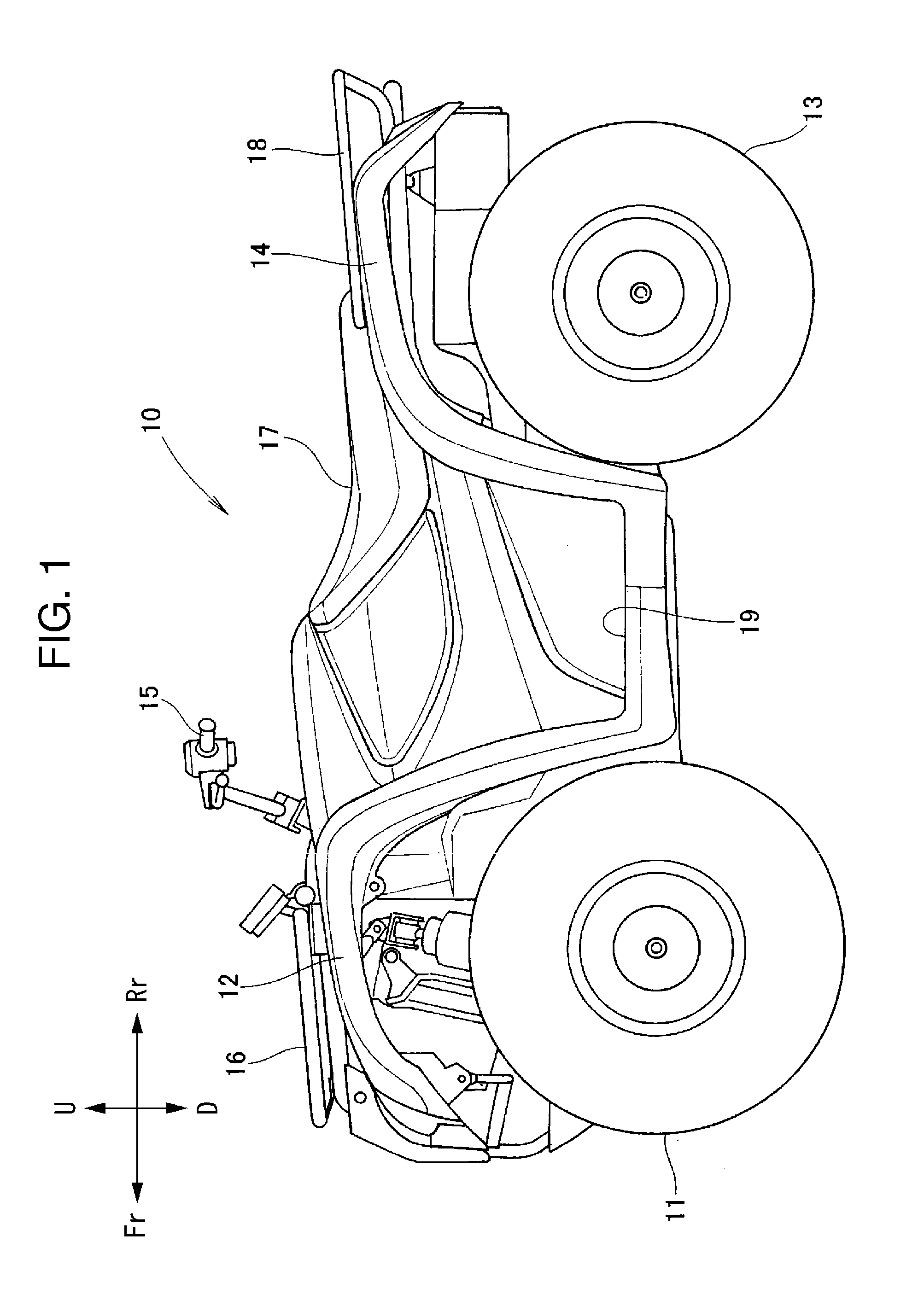
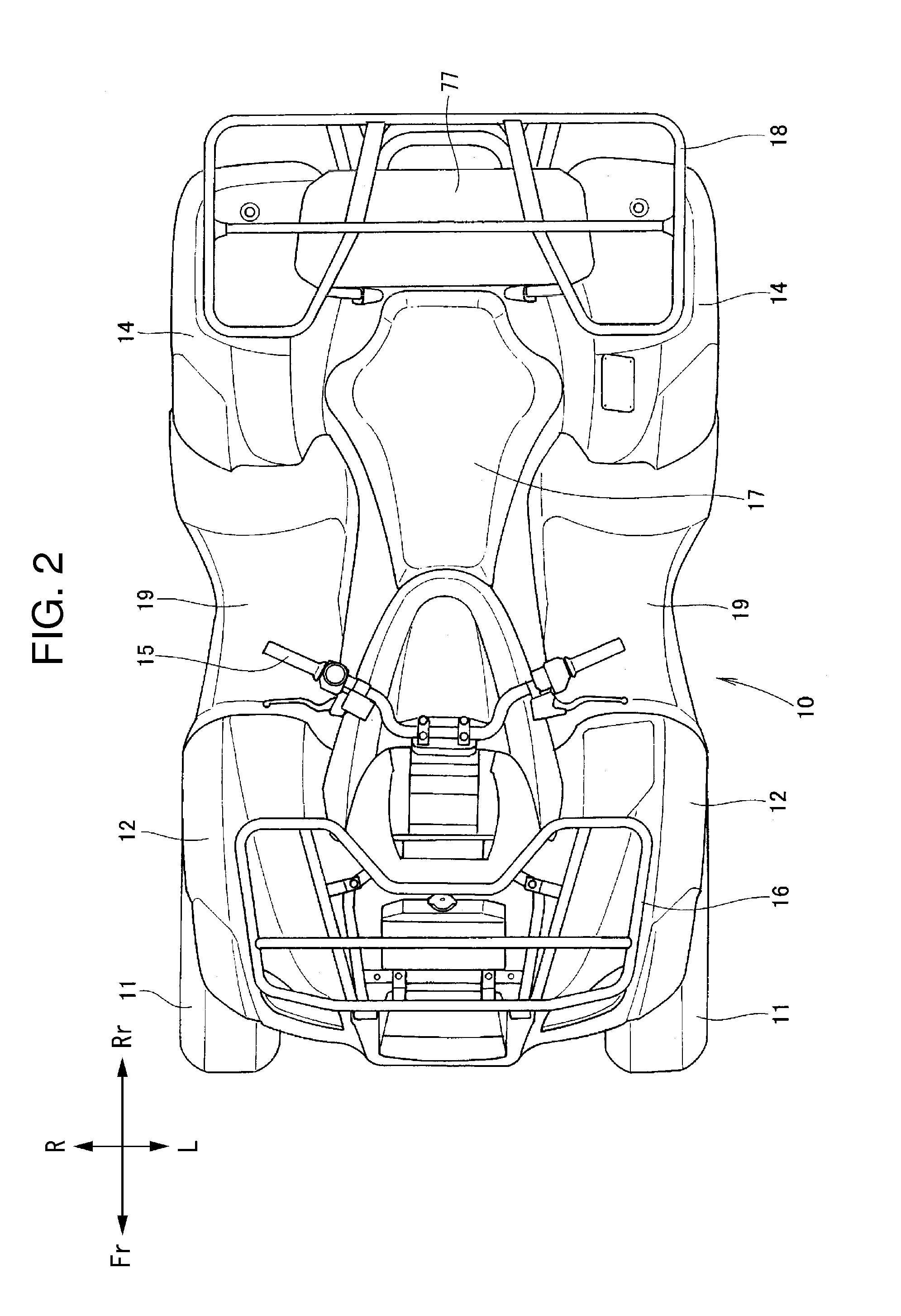
[0038]The embodiments of the present invention will be described below with reference to the attached drawings. The drawings should be viewed in the direction of the reference signs. In the following description, front and back, left and right, upper and lower are seen according to the direction of viewing from the rider. In the drawings, the front direction of the vehicle is denoted as FR, the rear direction is denoted as RR, the left is denoted as L, the right is denoted as R, upwards is denoted as U, and downwards is denoted as D.

[0039]As shown in FIG. 1, the vehicle 10 is a small vehicle that includes a front wheel 11 on a front lower portion of the vehicle body, a front fender 12 above the front wheel 11, a rear wheel 13 on a rear lower portion of the vehicle body, a rear fender 14 above the rear wheel 13, a steering handlebar 15 above the front wheel 11, a front carrier (luggage rack) 16 in front of the steering handlebar 15, and a riding seat 17 and a rear carrier (luggage ra...


PUM


Abstract

A vehicle includes a fuel tank, a canister for temporarily storing vaporized fuel from the fuel tank, a charge pipe that connects the fuel tank and the canister and that introduces vaporized fuel from the fuel tank to the canister, a purge pipe that connects the canister with an intake system of an internal combustion engine, and a vent pipe that connects the canister with ambient air outside of the canister. An opening of the vent pipe is arranged to open upwardly with respect to the vehicle body in a recessed portion that is formed in a hollow shape and opens downwardly in the vehicle body. A space is formed to partially open in an interval to a recessed portion sidewall of the recessed portion, and a locking member is also provided to cover the opening of the recessed portion from below.

Description

CROSS-REFERENCE TO RELATED APPLICATIONS[0001]The present invention claims priority under 35 USC 119 based on Japanese patent application No. 2010-083176, filed on Mar. 31, 2010. The subject matter of this priority document is incorporated by reference herein.BACKGROUND OF THE INVENTION[0002]1. Field of the Invention[0003]The present invention relates to a vehicle, and in particular to a vehicle adapted for rough terrain running, the vehicle including improved terminal structure of a vent pipe connected to an evaporative emissions canister of the vehicle.[0004]2. Background Art[0005]An evaporative emissions canister (also called “charcoal canister”) of a vehicle that is driven by an internal combustion engine is an apparatus that is interposed between a fuel tank and an engine, and has the function of temporarily storing vaporized fuel from the fuel tank, and supplying the vaporized fuel to the engine when engine operation is commenced.[0006]Activated carbon or the like is packed int...

Claims


Application Information

Patent Timeline
06 Oct 2011
Publication
US20110239994A1
IPC
F02M33/02
CPC
F02M25/0872; B62J35/00; F02M35/10222; B62K5/01
Inventors
HIRUKAWA, MASAYUKI