

Interconnects for photovoltaic panels
a photovoltaic panel and interconnection technology, applied in the direction of pv power plants, semiconductor devices, capacitors, etc., can solve the problems of low coefficient mismatch between glass and pv cells, interconnection failure, and breakage of the glass
- Summary
- Abstract
- Description
- Claims
- Application Information
AI Technical Summary
Benefits of technology
Problems solved by technology
Method used
Image

Examples
Embodiment Construction
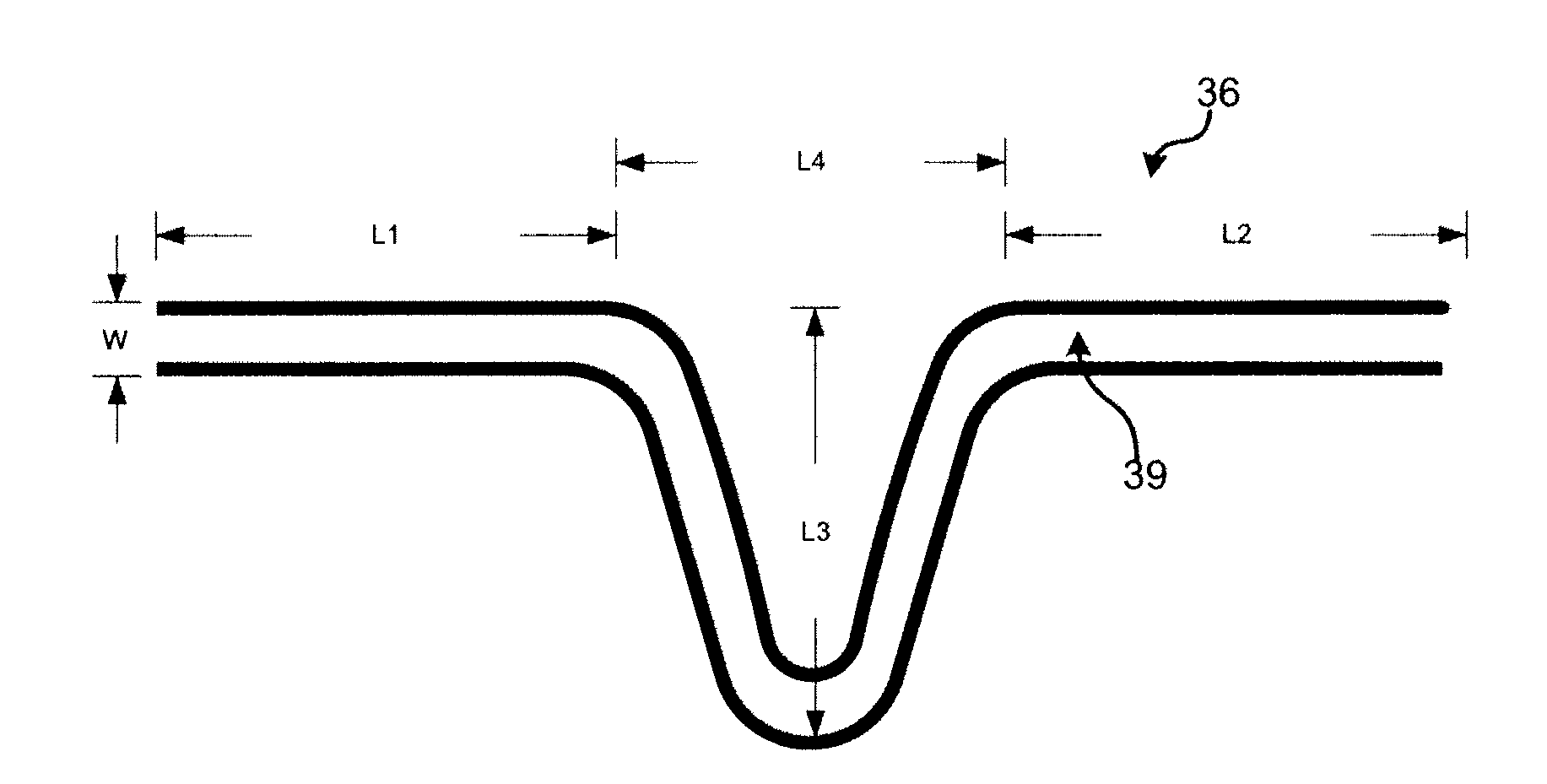
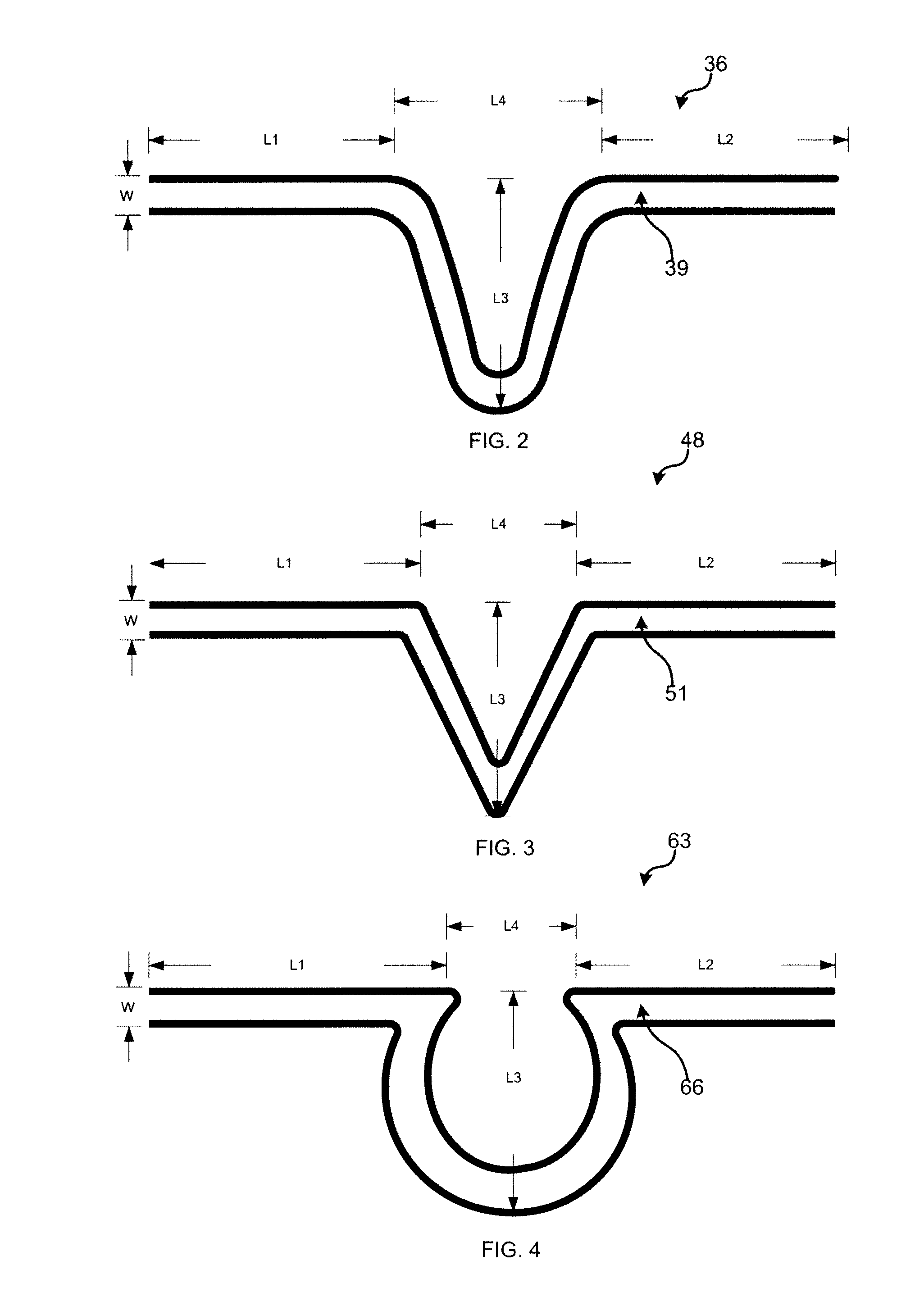
[0006]According to various embodiments of the invention, interconnects are provided, designed to be placed between layers of a photovoltaic (PV) laminate (i.e., in-plane) comprising photovoltaic (PV) cells, and designed to have built-in stress relief features, or sections, that compensate for stress from movement of the cells with respect to other components within the laminate. Additionally, in some embodiments, the interconnect is made of a single conductive wire, capable of being placed in one plane. In accordance with various embodiments of the present invention, the interconnect, once implemented into a photovoltaic laminate, can withstand at least repeated temperature cycles, for an extended period of time, without suffering failure (e.g., breakage). Such repeated temperature cycles are commonly performed under testing standards for photovoltaic products.
[0007]One embodiment of the present invention provides an interconnect for connecting a first photovoltaic cell to a bus arr...
PUM
| Property | Measurement | Unit |
|---|---|---|
| thickness | aaaaa | aaaaa |
| width | aaaaa | aaaaa |
| width | aaaaa | aaaaa |
Abstract
Description
Claims
Application Information