
Wireless power receiving apparatus and wireless power supply system

a power receiving apparatus and wireless technology, applied in the direction of transmission, transformers, inductances, etc., can solve the problems of difficult for ordinary coils to provide such a high q value, and difficult for small-size coils to provide such a high q value, and achieve high transmission efficiency, high-efficiency transmission, and extremely high coupling efficiency.

Active Publication Date: 2011-10-06
ADVANTEST CORP
View PDF4 Cites 73 Cited by
  • Summary
  • Abstract
  • Description
  • Claims
  • Application Information

AI Technical Summary

Benefits of technology

The present inventor has directed attention to the fact that the wireless resonance electric power supply technique provides high transmission efficiency between coils in a resonant state as long as the Q value is high even if the coupling coefficient is low (transmission efficiency∞k·Q) That is to say, by raising the Q value, such an arrangement has a potential to provide high-efficiency transmission even if the distance between the primary coil and the secondary coil is great, i.e., the coupling efficiency therebetween is extremely low (0.01 or less).
The present invention has been made in order to solve such a problem. Accordingly, it is an exemplary purpose of the present invention to provide a power reception circuit which is capable of providing a high Q value.
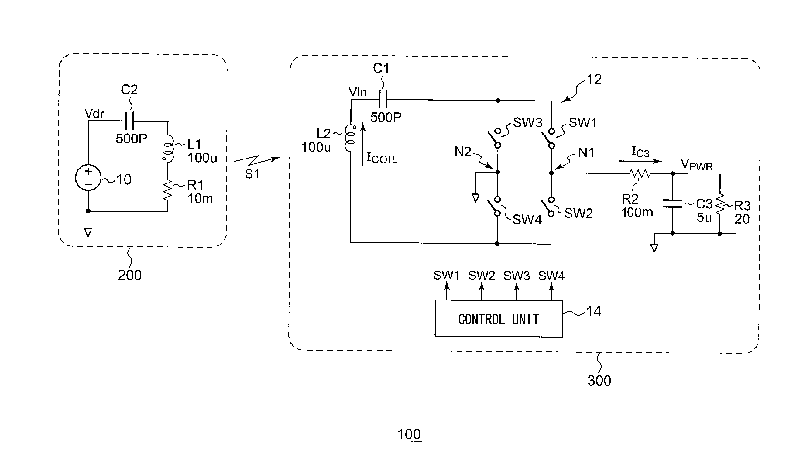
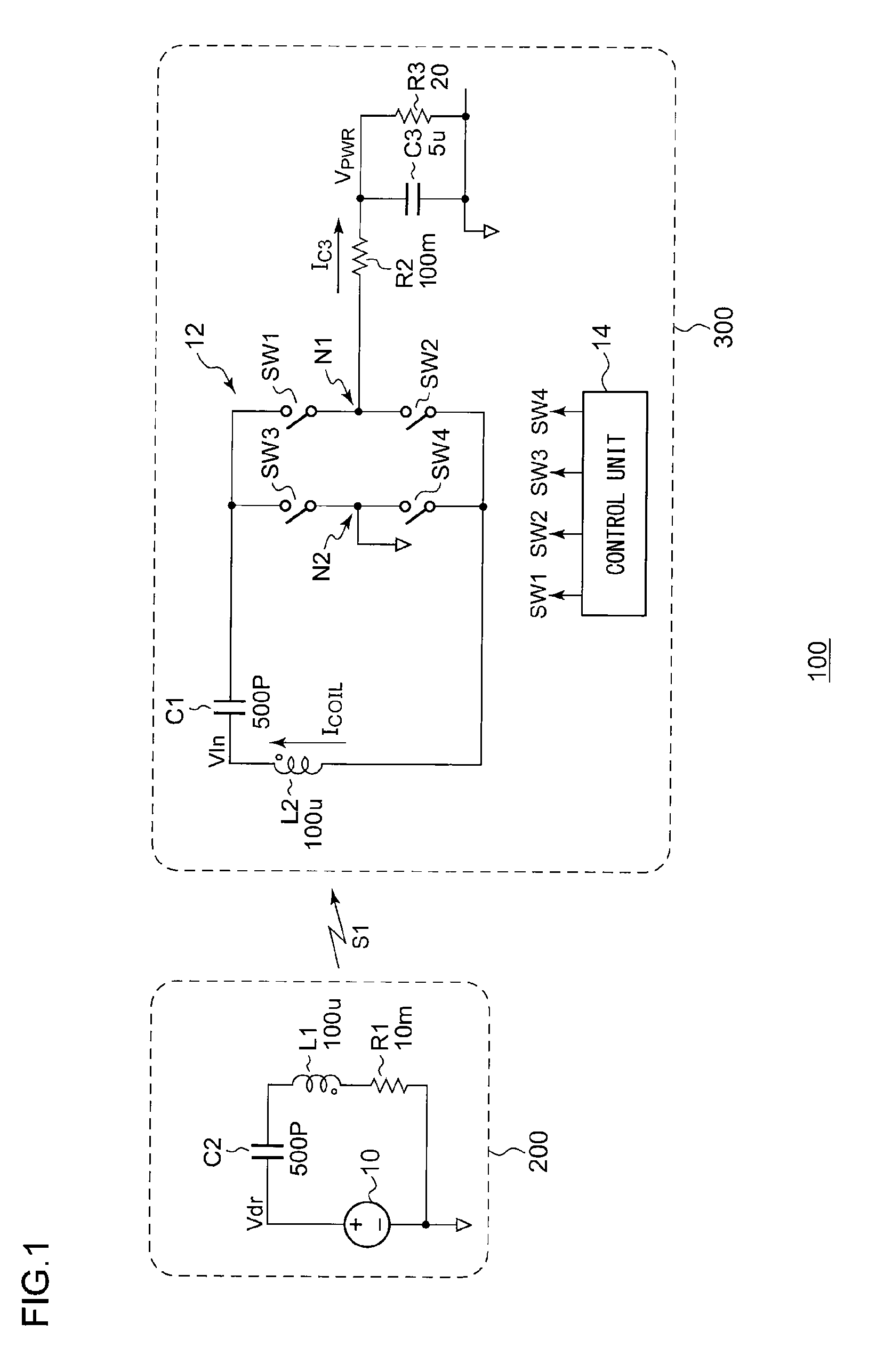
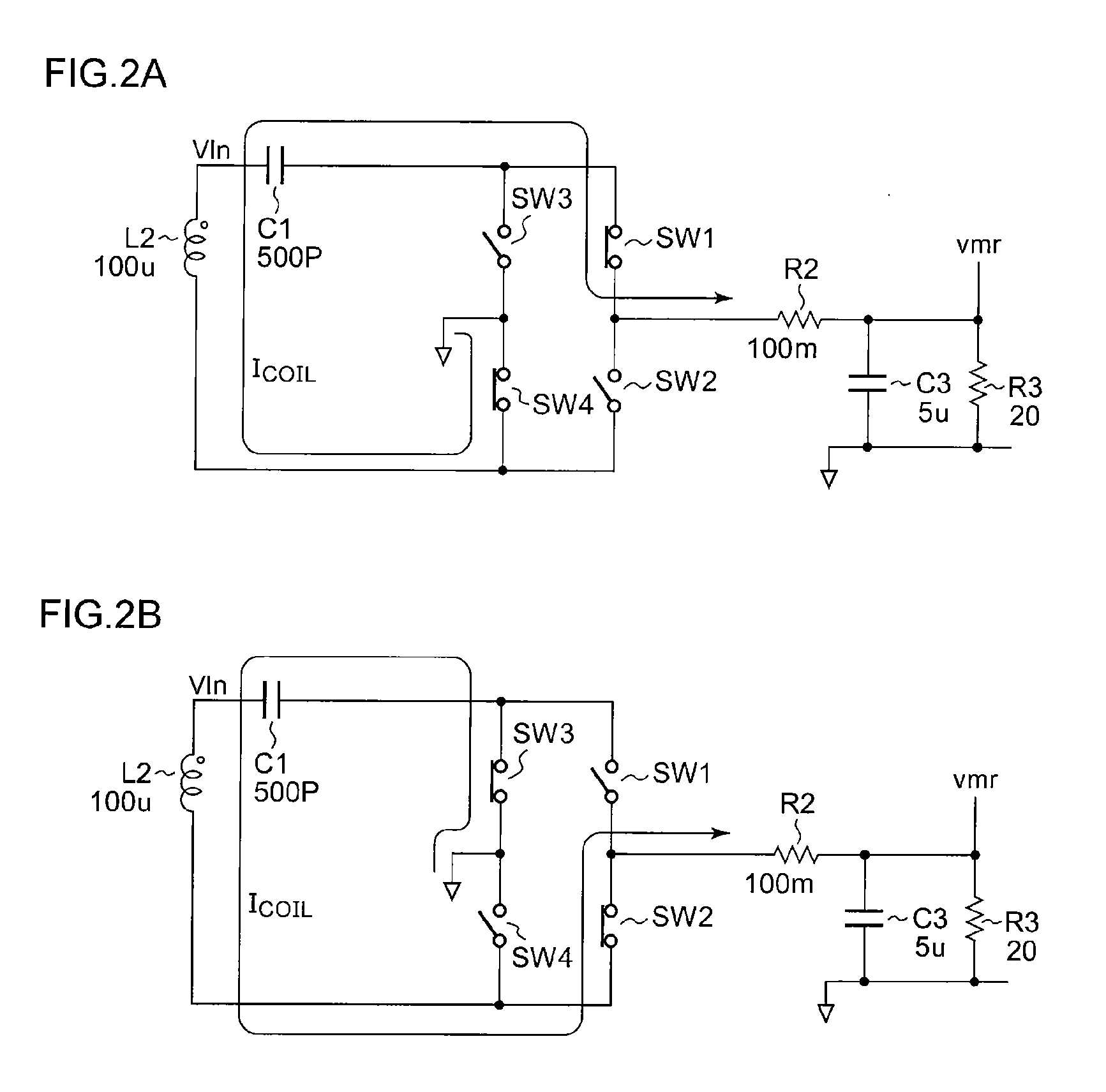
With such an embodiment, by appropriately controlling the first through fourth switches, such an arrangement is capable of raising the Q value of the circuit. Thus, such an arrangement provides high-efficiency power transmission even if the coupling efficiency is low between the wireless power supply apparatus and the wireless power receiving apparatus.

Problems solved by technology

However, it is difficult for ordinary coils to provide such a high Q value due to the wiring resistance and the skin effect.
In particular, it is difficult for a small-size coil to provide such a high Q value.

Method used


Image

  • Wireless power receiving apparatus and wireless power supply system
  • Wireless power receiving apparatus and wireless power supply system
  • Wireless power receiving apparatus and wireless power supply system

Examples


Embodiment Construction

The invention will now be described based on preferred embodiments which do not intend to limit the scope of the present invention but exemplify the invention. All of the features and the combinations thereof described in the embodiment are not necessarily essential to the invention.

In the present specification, the state represented by the phrase “the member A is connected to the member B” includes a state in which the member A is indirectly connected to the member B via another member that does not affect the electric connection therebetween, in addition to a state in which the member A is physically and directly connected to the member B.

Similarly, the state represented by the phrase “the member C is provided between the member A and the member B” includes a state in which the member A is indirectly connected to the member C, or the member B is indirectly connected to the member C via another member that does not affect the electric connection therebetween, in addition to a state...


PUM

PropertyMeasurementUnit
power use efficiencyaaaaaaaaaa
voltageaaaaaaaaaa
voltageaaaaaaaaaa

Abstract

A wireless power receiving apparatus receives an electric power signal including any one of an electric, magnetic, or electromagnetic field transmitted from a wireless power supply apparatus. A reception coil is configured to receive the electric power signal. A power storage capacitor is arranged having a first terminal set to a fixed electric potential. First and second switches are connected in series to form a closed loop including the reception coil. A connection node that connects these switches is connected to a second terminal of the power storage capacitor. Third and fourth switches are sequentially arranged in series to form a path arranged in parallel with a path comprising the first and second switches. A connection node that connects these switches is set to a fixed electric potential.

Description

BACKGROUND OF THE INVENTION1. Field of the InventionThe present invention relates to a wireless power supply technique.2. Description of the Related ArtIn recent years, wireless (contactless) power transmission has been receiving attention as a power supply technique for electronic devices such as cellular phone terminals, laptop computers, etc., or for electronic vehicles. Wireless power supply transmission can be classified into three principal methods using an electromagnetic induction, an electromagnetic wave reception, and an electric field / magnetic field resonance.The electromagnetic induction method is employed to supply electric power at a short range (several cm or less), which enables electric power of several hundred watts to be transmitted in a band that is equal to or lower than several hundred kHz. The power use efficiency thereof is on the order of 60% to 98%.In a case in which electric power is to be supplied over a relatively long range of several meters or more, th...

Claims


Application Information

Patent Timeline
Patent Type & Authority Applications(United States)
IPC IPC(8): H01F38/14
CPCH02J5/005H04B5/0093H04B5/0087H04B5/0037H02J50/12H04B5/263H04B5/266H04B5/79H02J50/40H02J50/005
Inventor FURUKAWA, YASUO
Owner ADVANTEST CORP
Learn More