Rotor of electric rotating machine

a rotating machine and electric technology, applied in the direction of magnetic circuit rotating parts, magnetic circuit shape/form/construction, windings, etc., can solve the problems of undetectable increase in the weight of the alternator, etc., to reduce the resistance or resistance of the magnetic force, reduce the total weight of the field coil, and shorten the length of the core layer unit in the axial direction

Active Publication Date: 2011-10-06
DENSO CORP
View PDF3 Cites 11 Cited by
  • Summary
  • Abstract
  • Description
  • Claims
  • Application Information

AI Technical Summary

Benefits of technology

[0014]An object of the present invention is to provide, with due consideration to the drawbacks of the conventional alternator, a rotor of an electric rotating machine which is lightened in weight so as to increase electric power generated per unit weight of the machine or rotational force generated per unit weight.
[0017]In this case, as compared with a conventional rotor having a single field coil and two rotor cores placing the coil between the cores, the number of turns in each field coil generating one of the distributed magnetic fluxes can be reduced so as to lighten the total weight of the field coils.
[0018]Further, because the core layer units are serially located along the axial direction, the length of each core layer unit in the axial direction is shortened, as compared with the conventional rotor. In this case, because the cores are necessarily thinned in the axial direction, the path of the magnetic flux passing through the cores while surrounding the field coil is shortened so as to reduce magnetic reluctance or resistance caused in the cores, and the difference in the path lengths of magnetic force lines in the cores is reduced so as to uniformly set the density of the magnetic flux in the cores. Therefore, the magnetic flux density can be heightened.
[0019]Accordingly, the rotor can be lightened in weight or can increase the magnetic flux density so as to increase the electric power or the rotational force generated per unit weight in the machine.

Problems solved by technology

However, the weight of the alternator disclosed in the Publication (No. 2008-054392) is undesirably increased by the magnets, and it is required to stably fix the magnets in the rotor.

Method used


Image

  • Rotor of electric rotating machine
  • Rotor of electric rotating machine
  • Rotor of electric rotating machine

Examples


first embodiment

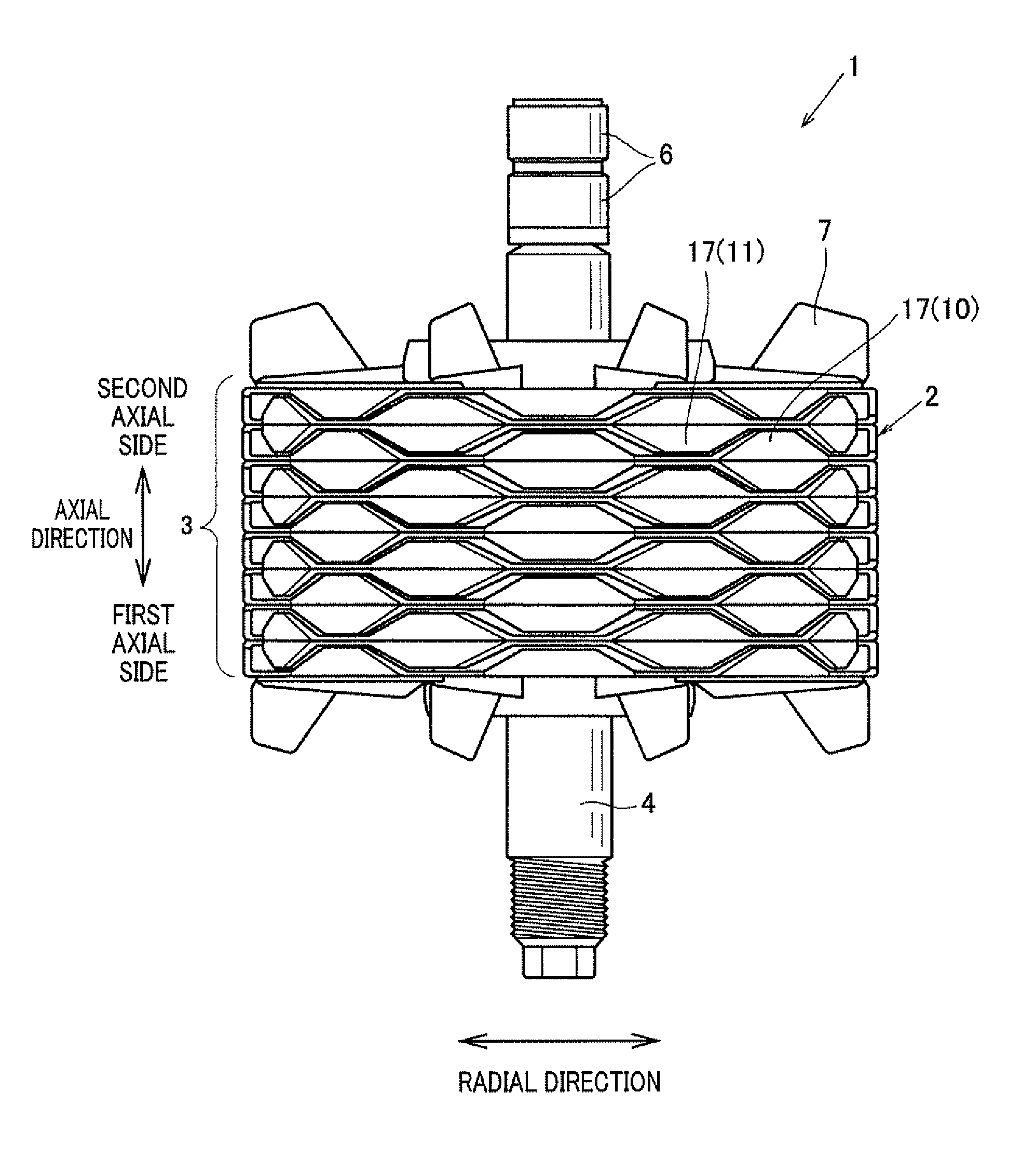
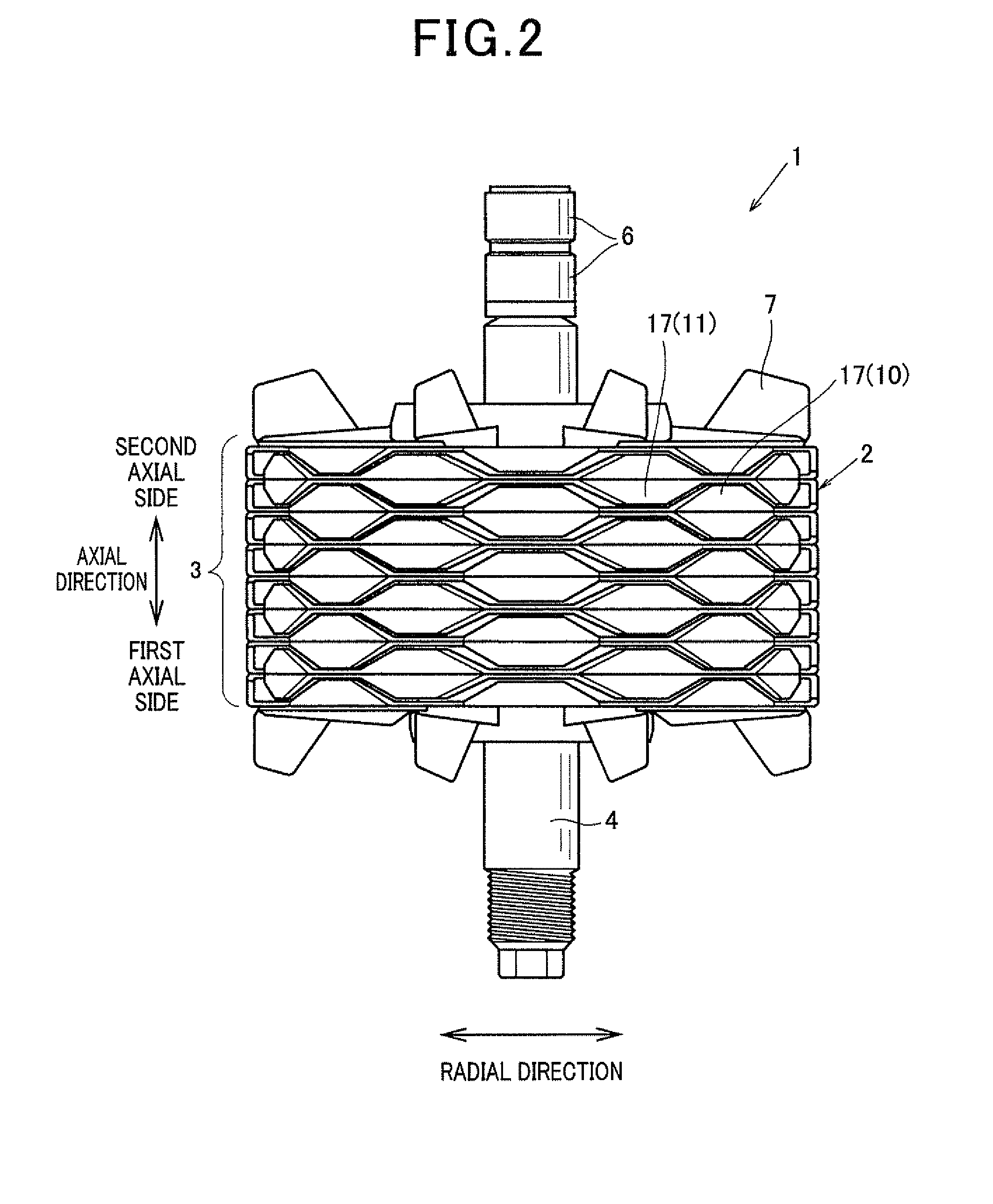
[0043]FIG. 2 is a side view of a rotor of an electric rotating machine according to the first embodiment, while FIG. 3 is a side view, partially in cross section, of the rotor. An electric rotating machine is, for example, used as an alternator mounted on a vehicle. As shown in FIG. 2 and FIG. 3, this alternator representing the machine has a rotor 1 and a cylindrically-shaped stator (not shown) surrounding the rotor 1 on the outer side of the rotor 1 in the radial direction of the rotor 1. The rotor 1 has a laminated body 3 formed in a torus or cylindrical shape, a rotational shaft 4 located along the central axis of the body 3 so as to revolve on its shaft center, two slip rings 6 attached to the shaft 4 such that electric current flows to the body 3 through the rings 6, fans 7 fixedly located on respective axial side surfaces of the body 3, and a spacer 8 located between the body 3 and the shaft 4 and fixed to the body 3 and the shaft 4. The spacer 8 is made of non-magnetic metal...

second embodiment

[0081]FIG. 11 is a side view, partially in cross section, of a rotor of an electric rotating machine according to the second embodiment. As shown in FIG. 11, a rotor 1A differs from the rotor 1 shown in FIG. 2 and FIG. 3 in that the rotor 1A has no spacer located between the laminated body 3 and the shaft 4. More specifically, each core layer unit 2 has a field coil 5A, a first rotor core 10A, a second rotor core 11A, a ring-shaped body 13A and a bobbin (not shown) assembled in the same manner as those in the unit 2 shown in FIG. 2 and FIG. 3. The coil 5A has an inner diameter and an outer diameter smaller than those in the coil 5 so as to approach the shaft 4. Each of the rotors 10A and 11A has a first yoke portion 15A having an outer diameter R2 smaller than that of the portion 15, a second yoke portion 16A extending from the portion 15A toward the outer side so as to substantially have the same outer diameter as that of the portion 16, and the magnetic poles 17 extending from the...

third embodiment

[0085]FIG. 12 is a side view of a rotor of an electric rotating machine according to the third embodiment, while FIG. 13 is an exploded view of rotor cores of one core layer unit of the rotor shown in FIG. 12. As shown in FIG. 12 and FIG. 13, a rotor 1B according to the third embodiment differs from the rotor 1 shown in FIG. 2 and FIG. 3 in that the width of each magnetic pole in the circumferential direction is narrowed step by step toward the top end of the pole.

[0086]More specifically, a plurality of claw-shaped magnetic poles 17B in the cores 10 differ from the poles 17 of the cores 10 shown in FIG. 4 and FIG. 5 in that each magnetic pole 17B has stepped ends on both sides in the circumferential direction to narrow the width toward the second axial side and to have at least one tread surface 35B, facing toward the second axial side, at each stepped end. A plurality of claw-shaped magnetic poles 17C in the cores 11 differ from the poles 17 of the cores 11 shown in FIG. 4 and FIG....


PUM


Abstract

A rotor of alternator has core layer units serially located along axial direction. Each unit has a field coil generating magnetic flux and two rotor cores receiving the flux on respective sides of the coil in axial direction. Each core has a first yoke portion located on inner side of the coil, a second yoke portion extending from the first yoke portion toward the outer side and magnetic poles extending from the second yoke portion in the axial direction. The poles of one core and the poles of the other core in each unit extend toward different axial sides and are alternately arranged in circumferential direction on the outer side of the coil. A ratio of the outer circumferential diameter of the first yoke portions to the rotational diameter of the poles is lower than 0.54.

Description

CROSS-REFERENCE TO RELATED APPLICATION[0001]This application is based upon and claims the benefit of priority of the prior Japanese Patent Application 2010-76652 filed on Mar. 30, 2010, so that the contents of which are incorporated herein by reference.BACKGROUND OF THE INVENTION[0002]1. Field of the Invention[0003]The present invention relates to a rotor of an electric rotating machine such as an alternator for a vehicle.[0004]2. Description of Related Art[0005]An alternator mounted on a vehicle has a cylindrically-shaped stator and a rotor located in the center space of the stator. FIG. 1 is a side view, partially in cross section, of a rotor of an alternator according to a prior art. As shown in FIG. 1, a rotor 100 of an alternator has a rotational shaft 104 revolving on its shaft center, a single core layer 102 rotated on its central axis with the shaft 104, slip rings 106 through which electric current flows to the core layer 102, and fans 107 located on respective sides of the...

Claims


Application Information

Patent Timeline
Patent Type & Authority Applications(United States)
IPC IPC(8): H02K3/28H02K1/22
CPCH02K1/243
Inventor TOKIZAWA, TAKASHI
Owner DENSO CORP
Why Eureka
Try Eureka