Signal processing apparatus and signal processing method

Inactive Publication Date: 2011-10-06
SONY CORP
View PDF3 Cites 67 Cited by
  • Summary
  • Abstract
  • Description
  • Claims
  • Application Information

AI Technical Summary

Benefits of technology

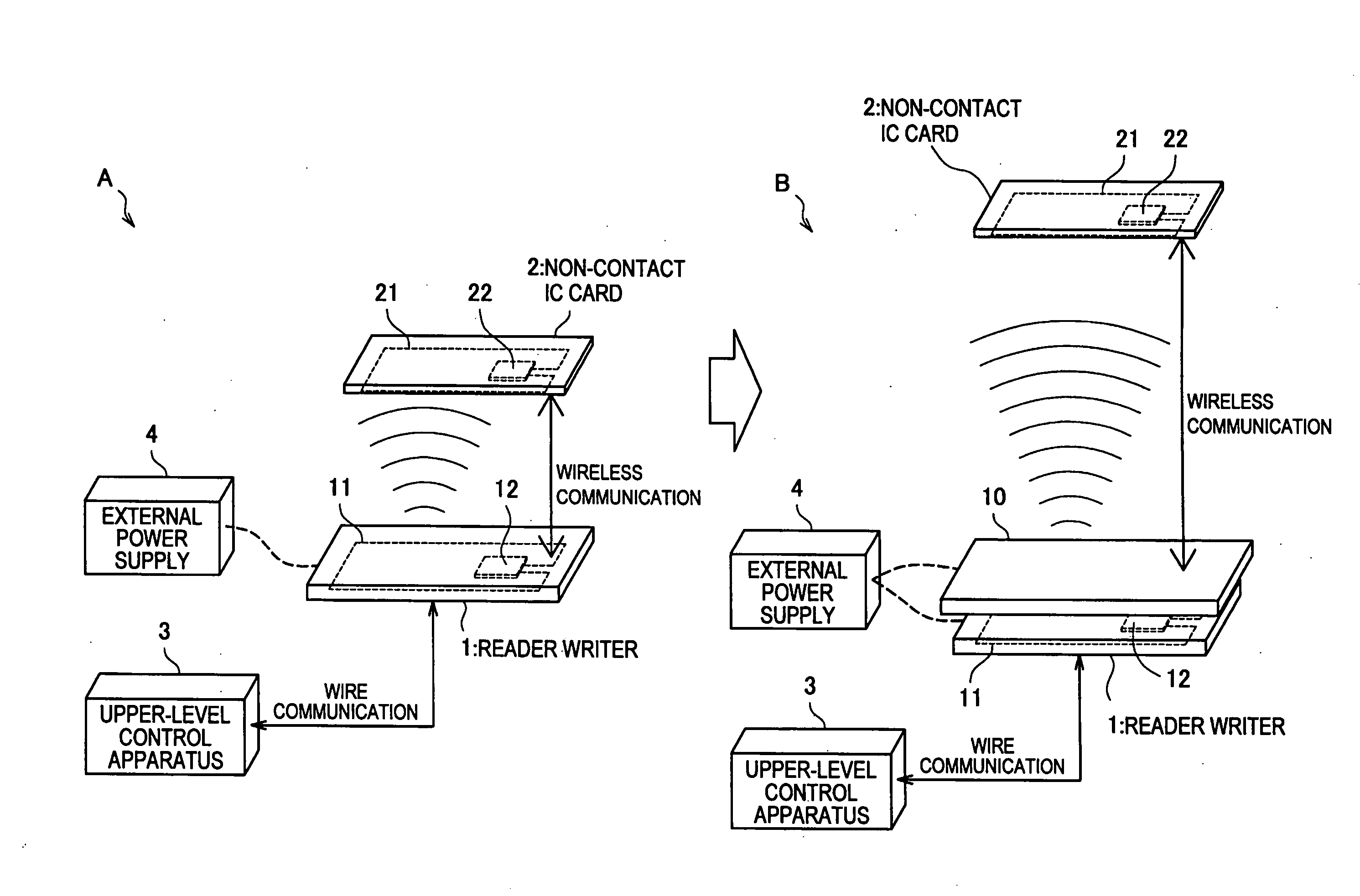
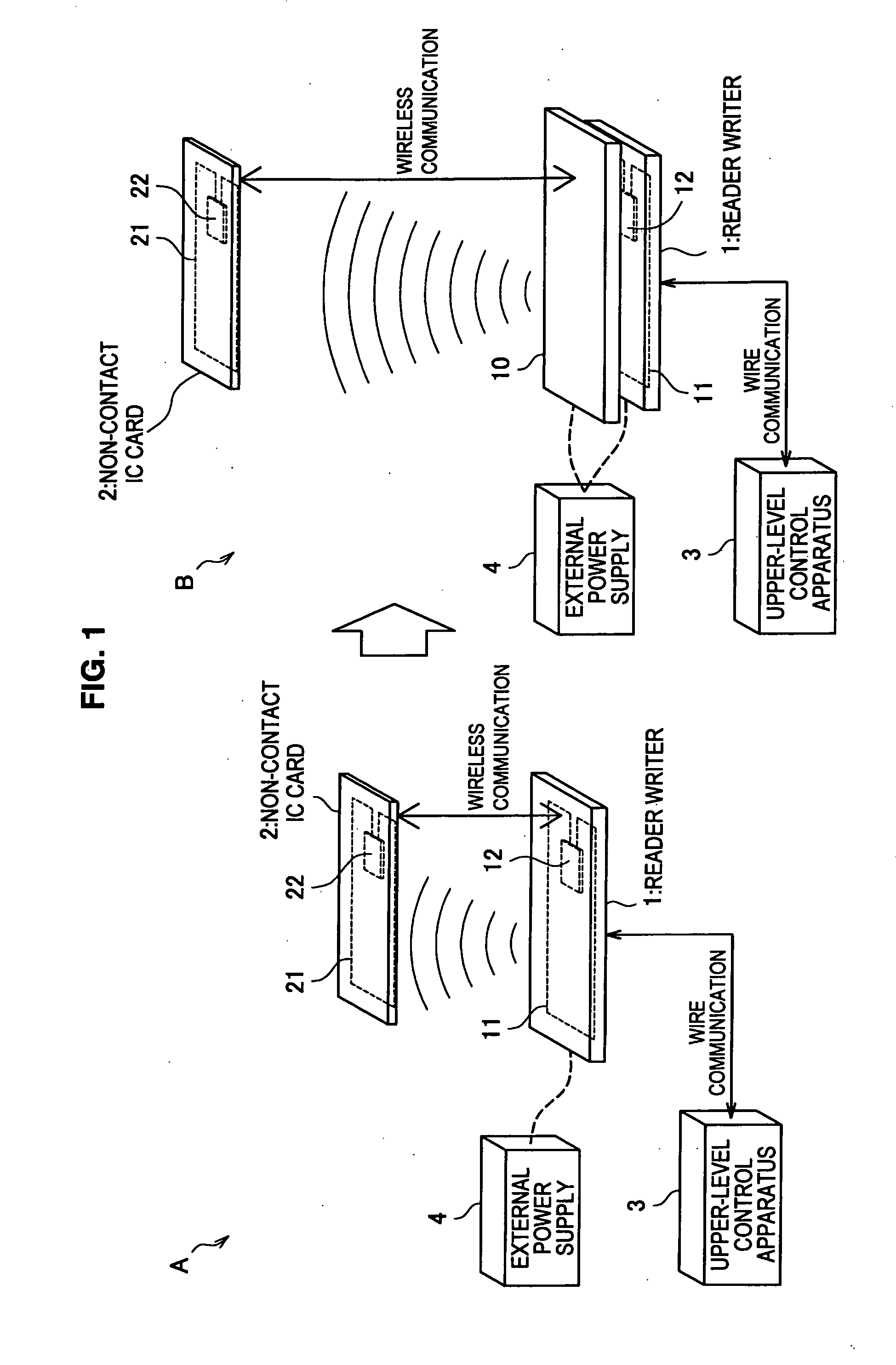
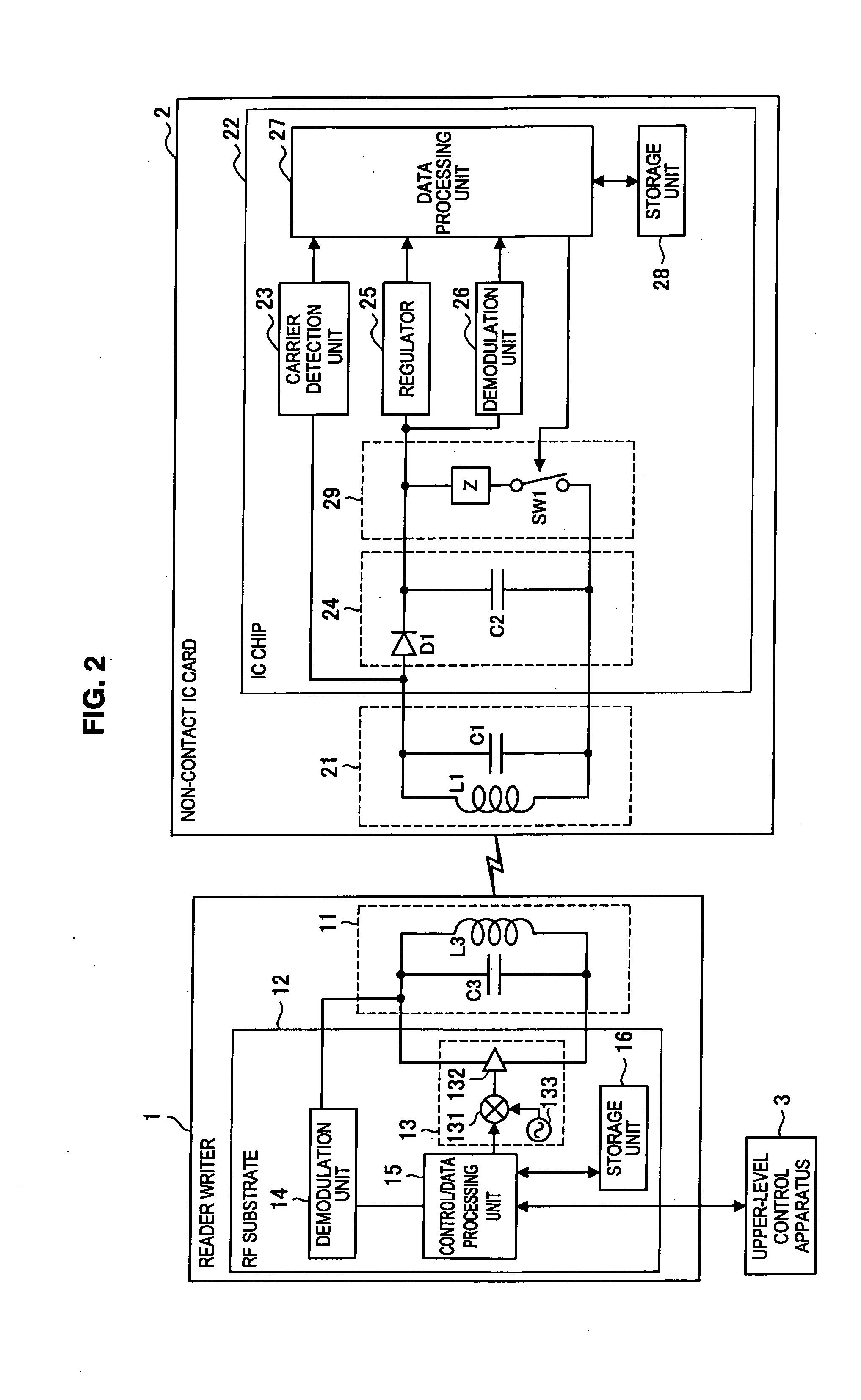
[0021]According to the above configuration, in a signal processing apparatus, a first carrier wave modulated with first data is received from a reader writer by using a first antenna, a second carrier wave is generated by the first carrier wave being amplified by using external power, the second carrier wave is modulated with the first data contained in the first carrier wave, the second carrier wave modulated with the first data is transmitted to the non-contact communication apparatus by using a second antenna, second data returned by load modulation of an antenna of the non-contact communication apparatus is received from the non-contact communication apparatus by using the second antenna, and the second data is transmitted to the reader writer by performing the load modulation that changes an impedance of the first antenna based on the second data. Accordingly,

Problems solved by technology

However, the technology to extend the communication distance of a reader writer by using a booster antenna in the related art described in Japanese Patent Application Laid-Open Nos. 2005-323019, 2008-306689, and 2000-138621 has issues described below.
Thus, an issue that the communication distance of the reader writer becomes shorter originating from an external metal body or antenna coil conditions (for example, an inductance L or capacitance C of the antenna or a coupling coefficient K (d) determined by antenna arrangement) could arise.
The reason therefor is that a decrease in magnetic flux (eddy current) caused by the external metal body, a shift of the resonance frequency between antenna coils (degradation in resonance), a decrease in electromagnetic coupling of antenna coils and the like adversely affect the communication distance of the reader writer.
Thus, it is difficult to decide each design valu

Method used


Image

  • Signal processing apparatus and signal processing method
  • Signal processing apparatus and signal processing method
  • Signal processing apparatus and signal processing method

Examples


application example

5. APPLICATION EXAMPLE

[0153]Next, an application example of the signal processing apparatus 10 according to the present embodiment will be described with reference to FIG. 7. FIG. 7 is a schematic diagram showing a communication system in which a plurality of the signal processing apparatuses 10 is arranged by being tilted with respect to the reader writer 1.

[0154]A booster antenna in the related art described in Japanese Patent Application Laid-Open Nos. 2005-323019, 2008-306689, and 2000-138621 has an issue that little effect of extending the communication distance in a horizontal direction with respect to a communication surface 5 of the reader writer 1 is achieved. The magnetic field 36 generated by the reader writer 1 spreads in a direction perpendicular to the communication surface and thus, the magnetic field can be expanded in the horizontal direction with respect to the communication surface 5 by enlarging the aperture (loop surface area) of the antenna coil of the reader w...


PUM


Abstract

There is provided a signal processing apparatus, including a first antenna to perform non-contact communication with a reader writer, a second antenna installed adjacent to the first antenna to perform the non-contact communication with a non-contact communication apparatus, a metal body that is arranged between the first antenna and the second antenna and blocks a magnetic field between the first antenna and the second antenna, an amplification unit that amplifies a carrier wave by using at least external power supplied from an external power supply, a modulation unit that modulates the carrier wave, and a load modulation unit that changes an impedance of the first antenna.

Description

BACKGROUND OF THE INVENTION[0001]1. Field of the Invention[0002]The present invention relates to a signal processing apparatus and a signal processing method.[0003]2. Description of the Related Art[0004]A communication system that performs non-contact communication of data between a non-contact IC card and a reader writer is used for various purposes such as a settlement terminal of a shop, an entry / departure control terminal of an office, and an automatic ticket examination of transportation facilities. To change such an installed and operated communication system as a whole or to change communication performance of a reader writer, a heavy investment in terms of cost and work load such as a modification or replacement of the reader writer and technical examination thereafter is necessary.[0005]If, for example, the communication distance of a reader writer installed in a shop should be extended or a communication area should be expanded in a horizontal direction, it is necessary to...

Claims


Application Information

Patent Timeline
IPC IPC(8): H04Q5/22
CPCH01Q1/2216G06K7/0008
Inventor SUZUKI, TAKAHIRO
Owner SONY CORP
Why Eureka
Try Eureka