Built-in antenna which supports broadband impedance matching and has feeding patch coupled to substrate

a broadband impedance matching and built-in antenna technology, applied in the field of antennas, can solve the problems of poor sar (specific absorption rate), difficult to provide an esthetic appearance and an external design, and achieve the effect of efficient utilization of spa

a broadband impedance matching and built-in antenna technology, applied in the field of antennas, can solve the problems of poor sar (specific absorption rate), difficult to provide an esthetic appearance and an external design, and achieve the effect of efficient utilization of spa

US20110241964A1Inactive Publication Date: 2011-10-06ACE TECH

Image

  • Built-in antenna which supports broadband impedance matching and has feeding patch coupled to substrate
  • Built-in antenna which supports broadband impedance matching and has feeding patch coupled to substrate
  • Built-in antenna which supports broadband impedance matching and has feeding patch coupled to substrate

Examples


Embodiment Construction

[0031]An internal antenna providing impedance matching for a wide band according to an embodiment of the invention will be described below in more detail with reference to the accompanying drawings.

[0032]An internal antenna providing impedance matching for a wide band according to an embodiment of the invention may be implemented with the use of a carrier, but for the sake of ease of explanation, first a description will be given of an antenna having a structure without a carrier with reference to FIGS. 1 to 4, and then later a description will be given of a structure implemented with a carrier.

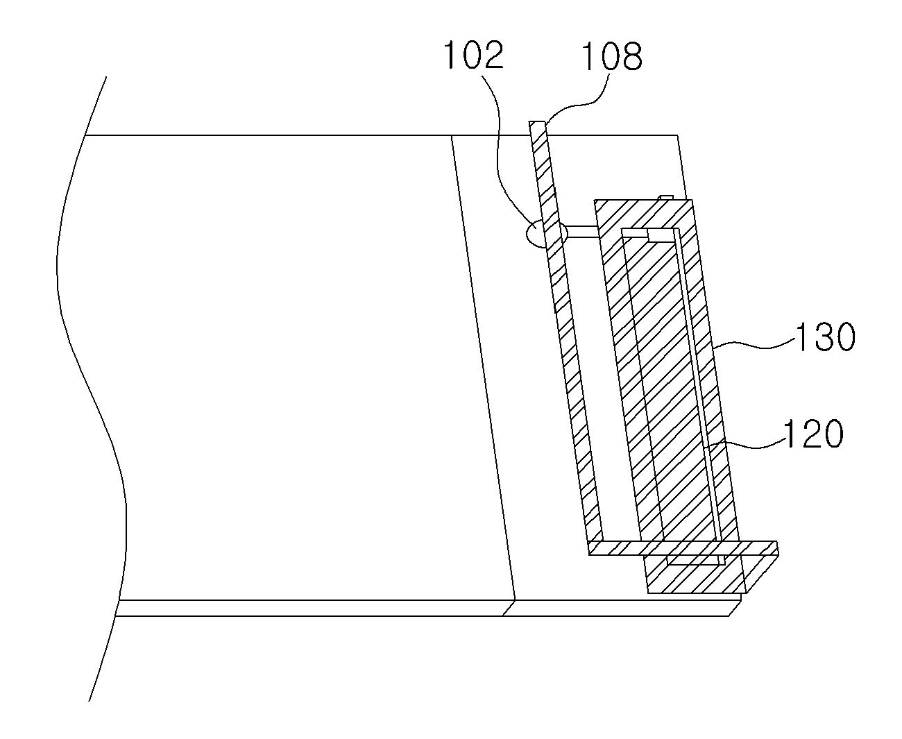
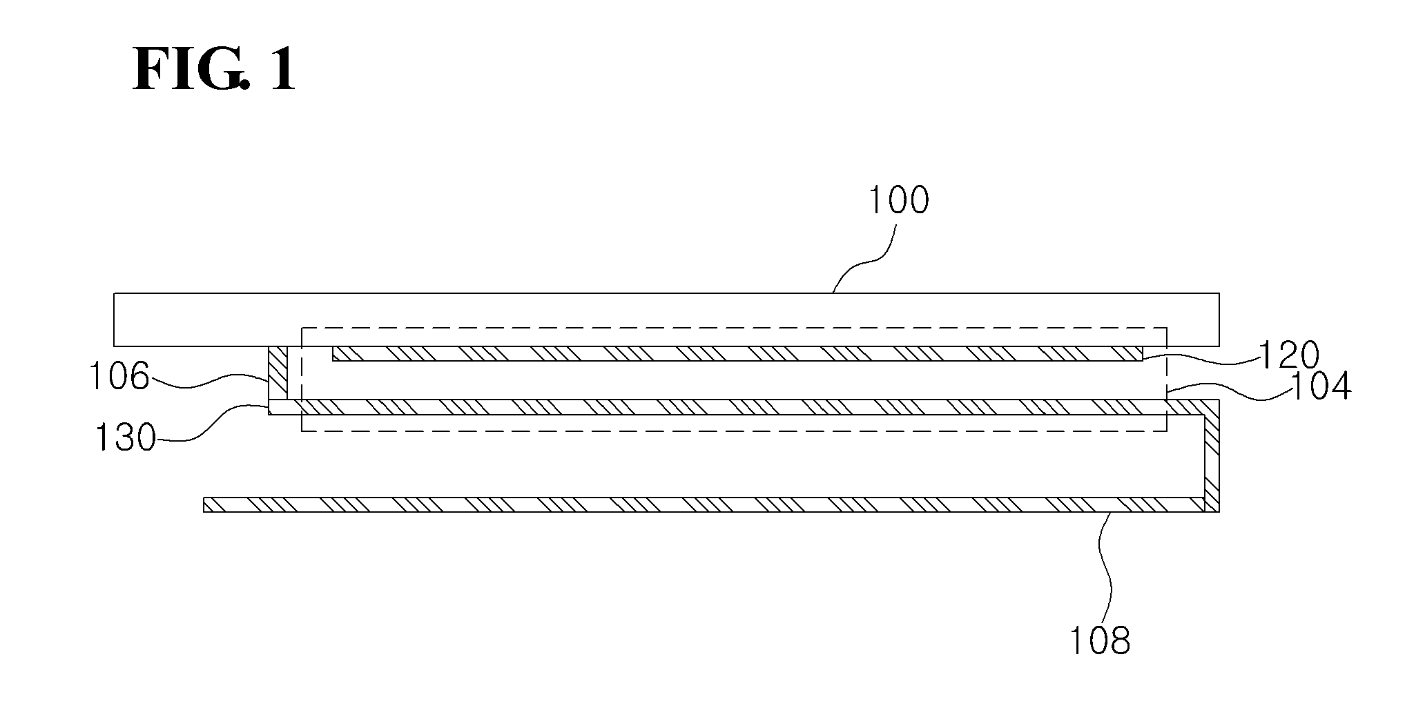
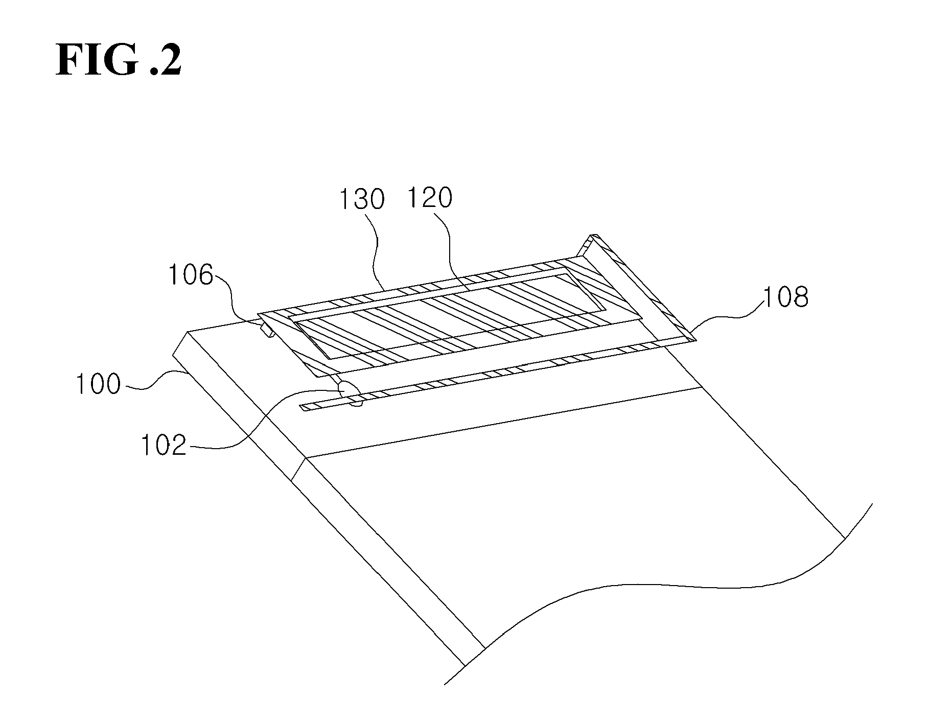
[0033]FIG. 1 is a cross-sectional view of an internal antenna for a wide band according to an embodiment of the present invention, FIG. 2 is a perspective view of an internal antenna for a wide band according to an embodiment of the present invention, and FIG. 3 is a perspective view of the internal antenna for a wide band according to an embodiment of the present invention as seen from anoth...


PUM


Abstract

Disclosed is an internal antenna providing impedance matching for a wide band where a feeding patch is placed on a substrate. The disclosed antenna may include: a substrate; an impedance matching / feeding unit including a feeding patch, which is formed on the substrate and electrically connected to a feeding point, and a ground patch, which is electrically connected to a ground and formed above the feeding patch separated at a designated distance from the feeding patch; and a radiator formed extending from the ground patch, where the impedance matching / feeding unit performs impedance matching by way of coupling between the feeding patch and the ground patch, and the radiator receives coupling feeding from the feeding patch. The disclosed antenna has the advantages of overcoming the narrow band problem of a planar inverted-F antenna, and of allowing more efficient utilization of space in an internal antenna for a wide band using coupling matching and coupling feeding.

Description

TECHNICAL FIELD[0001]The present invention relates to an antenna, more particularly to an internal antenna providing impedance matching for a wide band.BACKGROUND ART[0002]Recently there has been a demand for the ability to receive mobile communication services of different frequency bands through one mobile communication terminal, even as mobile communication terminals become smaller and lighter. There is a demand for terminals that are able to use signals of multiple bands simultaneously as necessary, for mobile communication services using a variety of frequency bands such as, for example, the CDMA service of the 824-894 MHz band and the PCS service of the 1750-1870 MHz, which have been commercialized in Korea, the CDMA service of the 832-925 MHz band, which has been commercialized in Japan, the PCS service of the 1850-1990 MHz band, which has been commercialized in the U.S., the GSM service of the 880-960 MHz band, which has been commercialized in Europe and China, and the DCS s...

Claims


Application Information

Patent Timeline
06 Oct 2011
Publication
US20110241964A1
IPC
H01Q1/50; H01Q1/48
CPC
H01Q1/241; H01Q9/0407; H01Q1/38; H01Q1/243; H01Q9/0442; H01Q9/045; H01Q5/50
Inventors
KIM, BYONG-NAM