Polarization-Independent Liquid Crystal Display Devices Including Multiple Polarization Grating Arrangements and Related Devices

a polarization-independent, liquid crystal display technology, applied in color television details, instruments, projectors, etc., can solve the problems of liquid crystal devices having significant optical power loss, affecting the performance of display, and losing at least 50% of the available light from the light sour

Active Publication Date: 2011-10-06
META PLATFORMS TECH LLC
View PDF0 Cites 87 Cited by
  • Summary
  • Abstract
  • Description
  • Claims
  • Application Information

AI Technical Summary

Benefits of technology

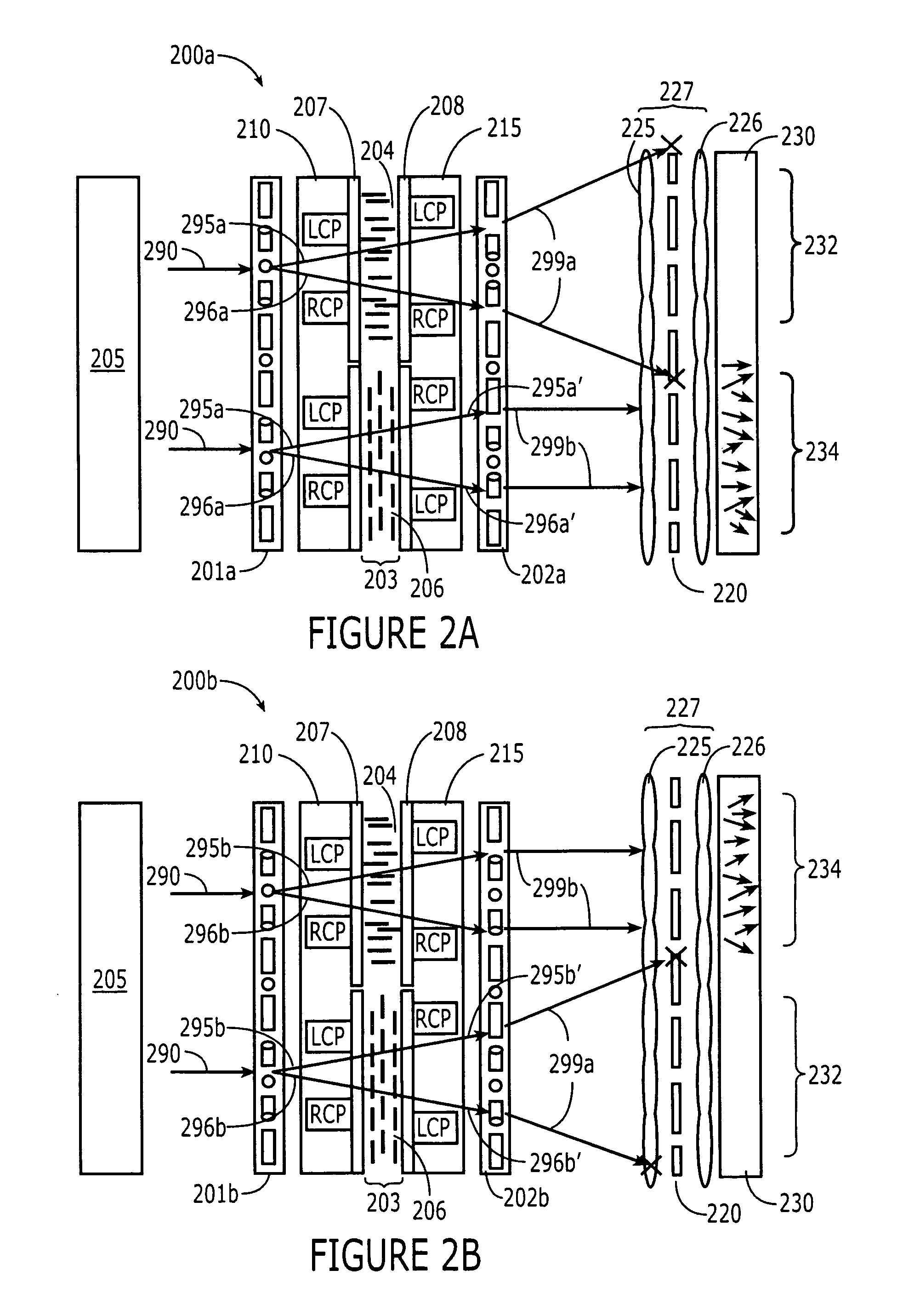
[0009]In some embodiments, the liquid crystal device may include an angle filtering stage configured to receive the output light transmitted from the second polarization grating. The angle filtering stage may be configured to block the output light that propagates at angles greater than a desired angle and direct the output light that propagates at angles less than the desired angle towards a screen. For example, the angle filtering stage may be configured to permit the output light that propagates in the direction substantially parallel to the incident light but block the output light that does not propagate in the direction substantially parallel to the incident light. In some embodiments, the angle filtering stage may include at least one lens and an aperture stop. In other embodiments, the angle filtering stage may be a privacy film.

Problems solved by technology

In optical applications, these domains and discontinuities may cause scattering of light, leading to degradation in the performance of the display.
However, since most light sources produce unpolarized light (e.g., fluorescent lamps, light emitting diodes, Ultra High Performance lamps, incandescent lamps), liquid crystal devices may use one or more linear polarizers to convert the unpolarized light from a light source into light of a desired polarization state.
As such, at least 50% of the available light from the light source may be lost, for example, as heat.
Liquid crystal devices may therefore have significant optical power losses (for example, greater than 50%), and as such, may require light sources more powerful than necessary.
This may be undesirable, for example, for reasons relating to power consumption, heat, and / or costs.

Method used


Image

  • Polarization-Independent Liquid Crystal Display Devices Including Multiple Polarization Grating Arrangements and Related Devices
  • Polarization-Independent Liquid Crystal Display Devices Including Multiple Polarization Grating Arrangements and Related Devices
  • Polarization-Independent Liquid Crystal Display Devices Including Multiple Polarization Grating Arrangements and Related Devices

Examples


Embodiment Construction

[0039]The present invention is described more fully hereinafter with reference to the accompanying drawings, in which embodiments of the invention are shown. This invention may, however, be embodied in many different forms and should not be construed as limited to the embodiments set forth herein. Rather, these embodiments are provided so that this disclosure will be thorough and complete, and will fully convey the scope of the invention to those skilled in the art. In the drawings, the size and relative sizes of layers and regions may be exaggerated for clarity. Like numbers refer to like elements throughout.

[0040]It will be understood that, although the terms first, second, third etc. may be used herein to describe various elements, components, regions, layers and / or sections, these elements, components, regions, layers and / or sections should not be limited by these terms. These terms are only used to distinguish one element, component, region, layer or section from another region...


PUM

PropertyMeasurementUnit
visible wavelengthaaaaaaaaaa
wavelength rangeaaaaaaaaaa
transmittanceaaaaaaaaaa

Abstract

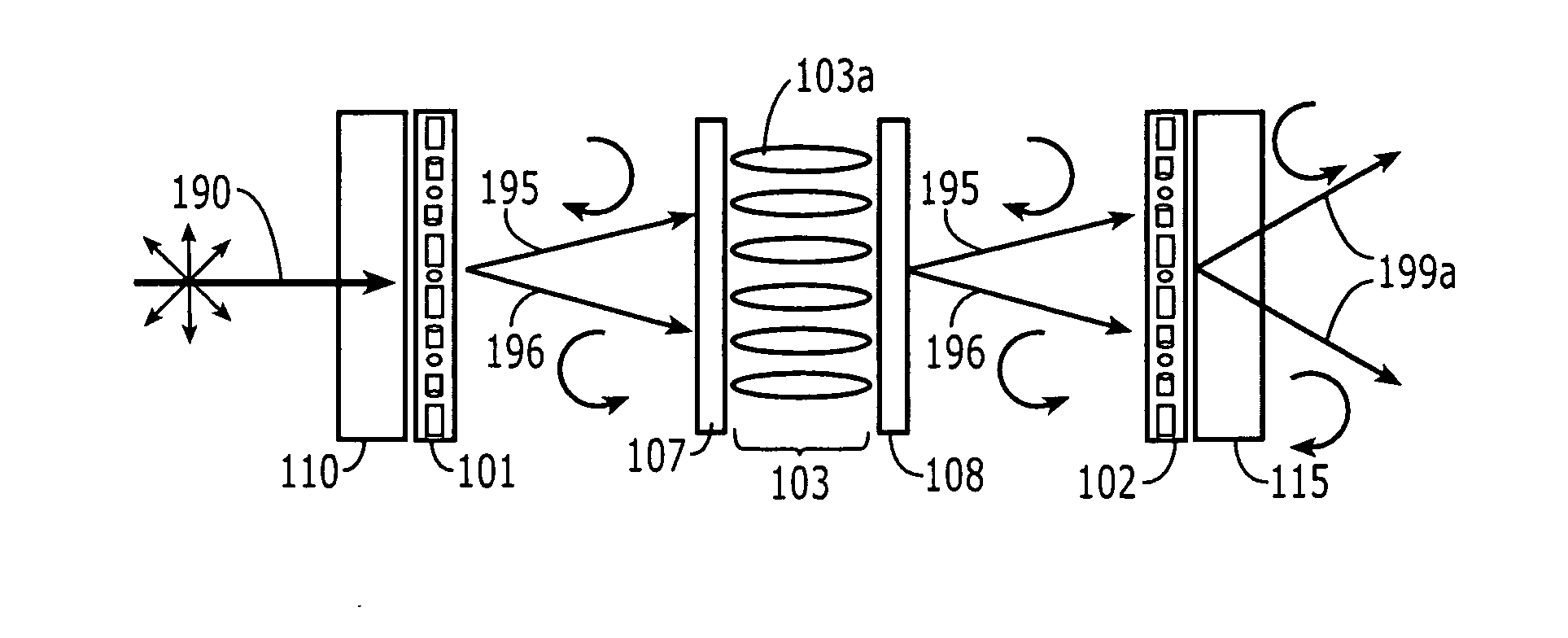
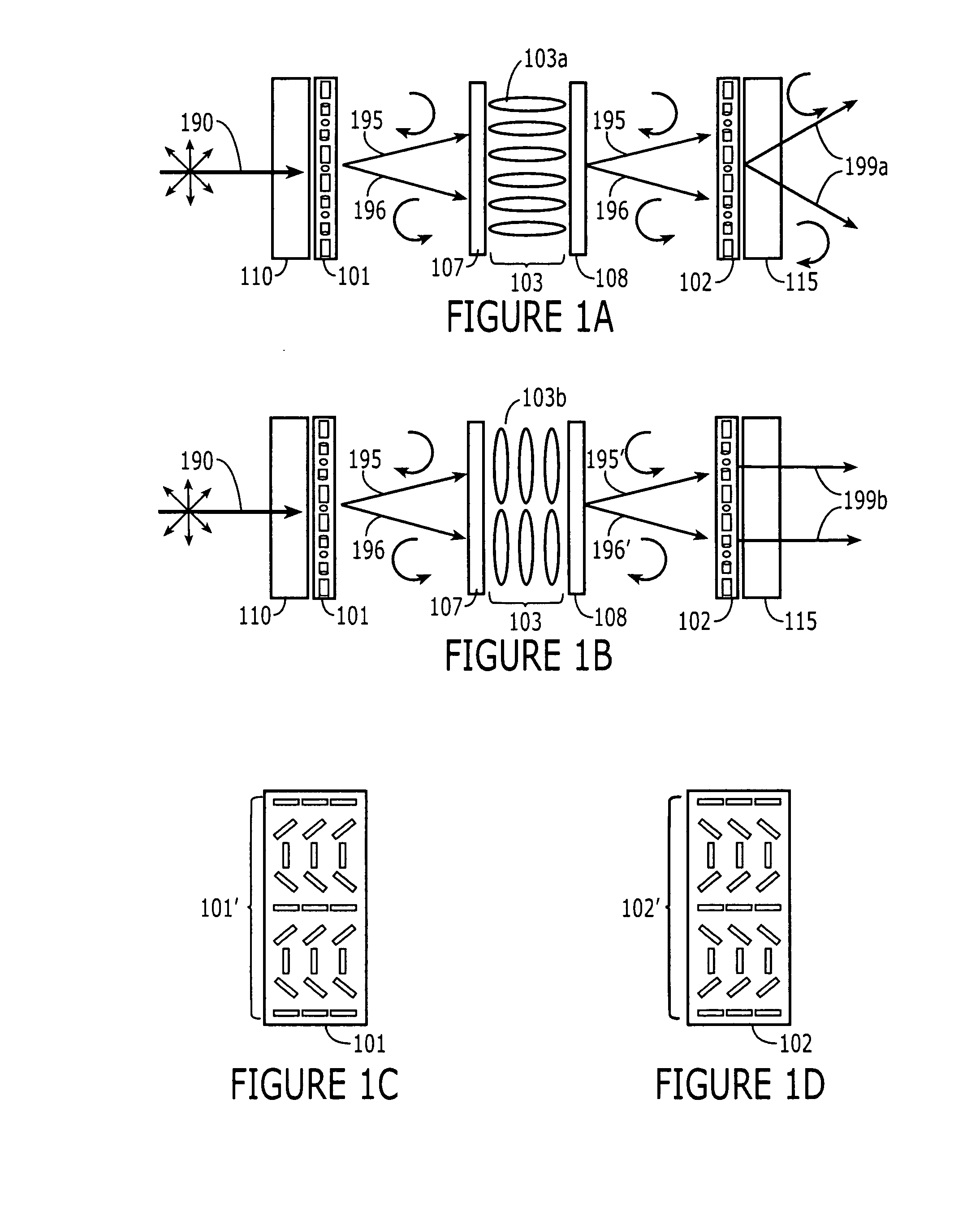
A liquid crystal device includes a first polarization grating (101), a second polarization grating (102), and a liquid crystal layer (103). The first polarization grating (101) is configured to polarize and diffract incident light (190) into first and second beams (195,196) having different polarizations and different directions of propagation relative to that of the incident light (190). The liquid crystal layer (103) is configured to receive the first and second beams (195,196) from the first polarization grating (101). The liquid crystal layer (103) is configured to be switched between a first state that does not substantially affect respective polarizations of the first and second beams (195,196) traveling therethrough, and a second state that alters the respective polarizations of the first and second beams (195,196) traveling therethrough. The second polarization grating (102) is configured to analyze and diffract the first and second beams (195,196) from the liquid crystal layer (103) to alter the different directions of propagation thereof in response to the state of the liquid crystal layer (103). Related devices are also discussed.

Description

STATEMENT OF GOVERNMENT SUPPORT[0001]This invention was made with Government support by the National Science Foundation (NSF) under contract 0621906. The U.S. Government has certain rights to this invention.FIELD OF THE INVENTION[0002]The present invention relates to liquid crystal displays, and more particularly, to liquid crystal polarization gratings and related methods of fabrication.BACKGROUND OF THE INVENTION[0003]Liquid crystals may include liquids in which an ordered arrangement of molecules exists. Typically, liquid crystal (LC) molecules may be anisotropic, having either an elongated (rod-like) or flat (disk-like) shape. As a consequence of the ordering of the anisotropic molecules, a bulk LC often exhibits anisotropy in its physical properties, such as anisotropy in its mechanical, electrical, magnetic, and / or optical properties.[0004]As a result of the rod-like or disk-like nature, the distribution of the orientation of LC molecules may play an important role in optical ...

Claims


Application Information

Patent Timeline
Patent Type & Authority Applications(United States)
IPC IPC(8): G02F1/1335
CPCG02F1/133504G02F1/133524G02F1/133526G02F1/1393H04N9/3167G02F2001/133742G02F2201/305G02F2203/06G03B21/006G02F2001/133543G02F1/133543G02F1/133742
Inventor ESCUTI, MICHAEL JAMESOH, CHULWOOKOMANDURI, RAVICONOVER, BRANDON L.KIM, JIHWAN
Owner META PLATFORMS TECH LLC
Why Eureka
Try Eureka