Eureka AIR delivers breakthrough ideas for toughest innovation challenges, trusted by R&D personnel around the world.

Method for accomplishing high-speed intensity variation of a polarized output laser beam

Inactive Publication Date: 2011-10-06
ELECTRO SCI IND INC
View PDF5 Cites 2 Cited by
  • Summary
  • Abstract
  • Description
  • Claims
  • Application Information

AI Technical Summary

Benefits of technology

[0005]A preferred method of accomplishing high-speed intensity variation of a polarized output laser beam entails generating an input laser beam propagating along a first portion of a beam path toward a target location on a workpiece. The method also includes providing a galvanometer system including a galvanometer drive member cooperating with a rotatable drive shaft to rotate the rotatable drive shaft about a rotation axis that is transverse to the first portion of the beam path. The galvanometer drive member controls rotation of the rotatable drive shaft to provide high-speed transitioning of the rotatable drive shaft between selected angular positions.
[0006]An angle of light incidence sensitive optical element secured to the rotatable drive shaft enables rotation of the angle of light incidence sensitive optical element about the rotation axis. The angle of light incidence sensitive optical element includes a planar optical film positioned to intersect the first portion of the beam path so that the input laser beam is incident on the planar optical film at an angle of incidence determined by an angular position of the rotatable drive shaft. The planar optical film produces from the input laser beam a polarized output laser beam that propagates along a second portion of the beam path toward the target location on the workpiece. The polarized output laser beam is characterized by an intensity that varies as a function of the angle of incidence between the input laser beam and the planar optical film. The high-speed transitioning of the rotatable drive shaft by the galvanometer drive member changes the angle of incidence between the input laser beam and the planar optical film to thereby accomplish high-speed variation of the intensity of the polarized output laser beam.

Problems solved by technology

Although an AOM can quickly vary beam intensity (in about 100 nanoseconds or less), a system implementing an AOM is typically complex, optical alignment of the system is relatively challenging, and the beam path is relatively long.

Method used


Image

  • Method for accomplishing high-speed intensity variation of a polarized output laser beam
  • Method for accomplishing high-speed intensity variation of a polarized output laser beam
  • Method for accomplishing high-speed intensity variation of a polarized output laser beam

Examples


Embodiment Construction

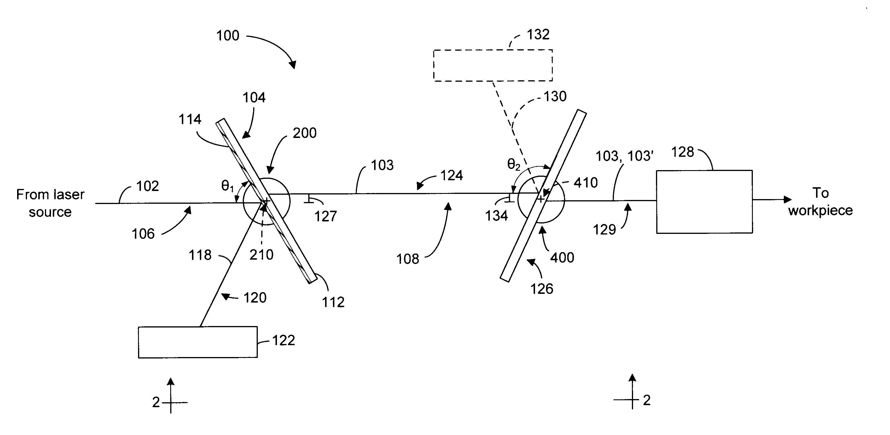
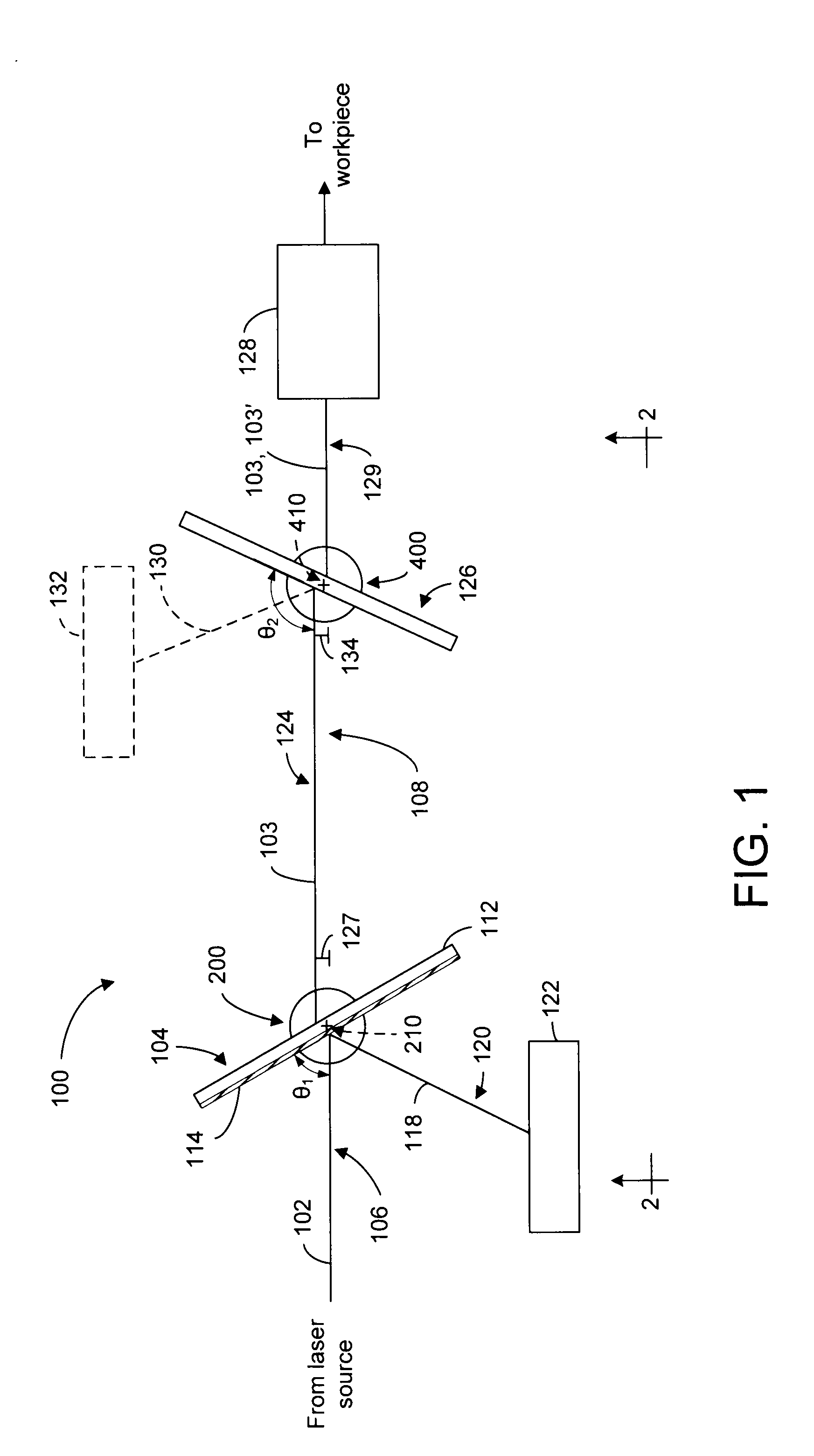
[0011]FIG. 1 is a schematic block diagram showing the hardware architecture of an embodiment of a system 100 for selectively attenuating an input laser beam 102 to produce a polarized output laser beam 103 of varying intensity (e.g., power level). Input laser beam 102 includes p-polarized light and, preferably, excludes substantially all s-polarized light. Input laser beam 102 is generated by a conventional laser source (not shown), such as, but not limited to, an ultraviolet (UV) laser source (e.g., a 355 nm laser). System 100 includes an angle of light incidence sensitive optical element 104 positioned to intersect a first portion 106 of a beam path 108 along which input laser beam 102 propagates towards a target location on a workpiece (not shown). In one example, optical element 104 is a polarizer, preferably a thin-film polarizer. However, any other optical element may be used that is characterized by an incident light transmission efficiency that varies as a function of an ang...


PUM


Abstract

A method of accomplishing high-speed intensity variation of a polarized output laser beam includes securing an angle of light incidence sensitive optical element to a galvanometer system that provides high-speed transitioning of the angle of light incidence sensitive optical element between different angular positions. The high-speed transitioning provided by the galvanometer system varies an angle of incidence between an input laser beam and the angle of light incidence sensitive optical element to thereby provide high-speed variation of an intensity of a polarized output laser beam produced by the angle of light incidence sensitive optical element.

Description

TECHNICAL FIELD[0001]This disclosure relates to optical systems and, in particular, to a laser beam optical system and method for varying the intensity of a polarized output laser beam.BACKGROUND INFORMATION[0002]In many laser processing applications, the intensity of a polarized laser beam is varied (e.g., attenuated) using an optical attenuator. In one conventional approach, a combination of a rotating waveplate (or an electro-optic modulator (EOM)) and a subsequent polarizer are used to produce a polarized laser beam having a variable intensity. For example, in a system using a rotating waveplate and subsequent polarizer, the rotating waveplate and subsequent polarizer are positioned in a beam path of a laser beam, and the rotating waveplate is rotated about an axis parallel to the beam path to rotate a polarization vector, which changes the intensity of a polarized laser beam exiting the subsequent polarizer. In another conventional approach, an acousto-optic modulator (AOM) is ...

Claims


Application Information

Patent Timeline
IPC IPC(8): G02B26/04
CPCG02B26/02G02B27/281G02B26/04H01S3/10H01S3/101
Inventor KLEINERT, JAN
Owner ELECTRO SCI IND INC
Why Eureka
Eureka Blog
Learn More