Illumination light source and two-dimensional image display using same

a light source and light source technology, applied in the direction of picture reproducers, picture reproducers using projection devices, instruments, etc., can solve the problems of difficult to increase the amplitude by a normal driving method, and the driving is not stabilized, so as to achieve uniform illumination of the screen or the lik

Active Publication Date: 2006-12-21
PANASONIC CORP
View PDF8 Cites 49 Cited by
  • Summary
  • Abstract
  • Description
  • Claims
  • Application Information

AI Technical Summary

Benefits of technology

[0006] The invention therefore has an object to solve these problems and provide a compact, highly silent illumination light source capable of illuminating a screen or the like uniformly, and a 2-D image display device using the same.
[0011] Accordingly, the correction optical system makes a correction in such a manner that, for example, the scan rate becomes lower in a region where the scan angle is small and the scan rate becomes higher in a region where the scan angle is large. It is thus possible to achieve a compact, highly silent illumination light source capable of illuminating the screen or the like uniformly.

Problems solved by technology

Also, in a case where the mirror portion provided to the beam scan means is driven, it is difficult to increase the amplitude by a normal driving method; moreover, driving is not stabilized due to an inhomogeneous driving force and air resistance.

Method used


Image

  • Illumination light source and two-dimensional image display using same
  • Illumination light source and two-dimensional image display using same
  • Illumination light source and two-dimensional image display using same

Examples


first embodiment

[0020] One embodiment of the invention will now be described in detail with reference to the drawings.

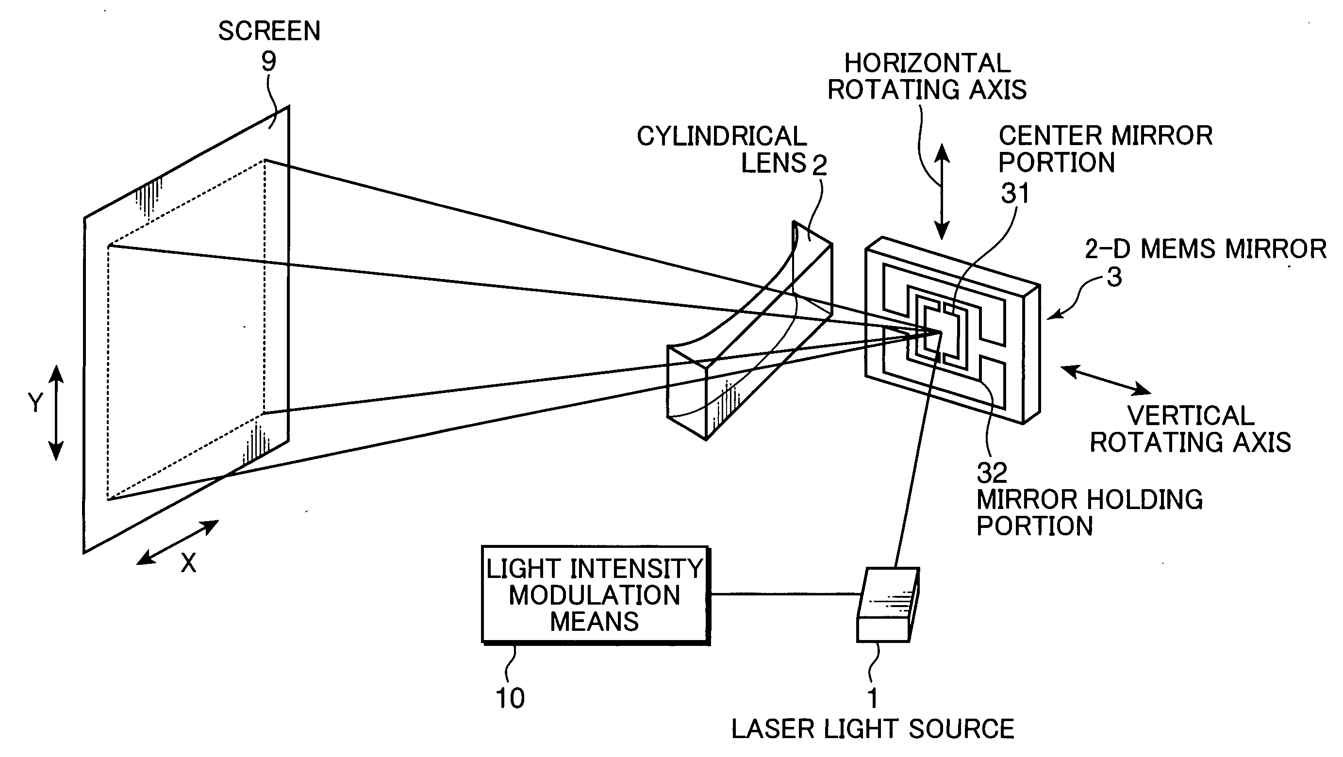
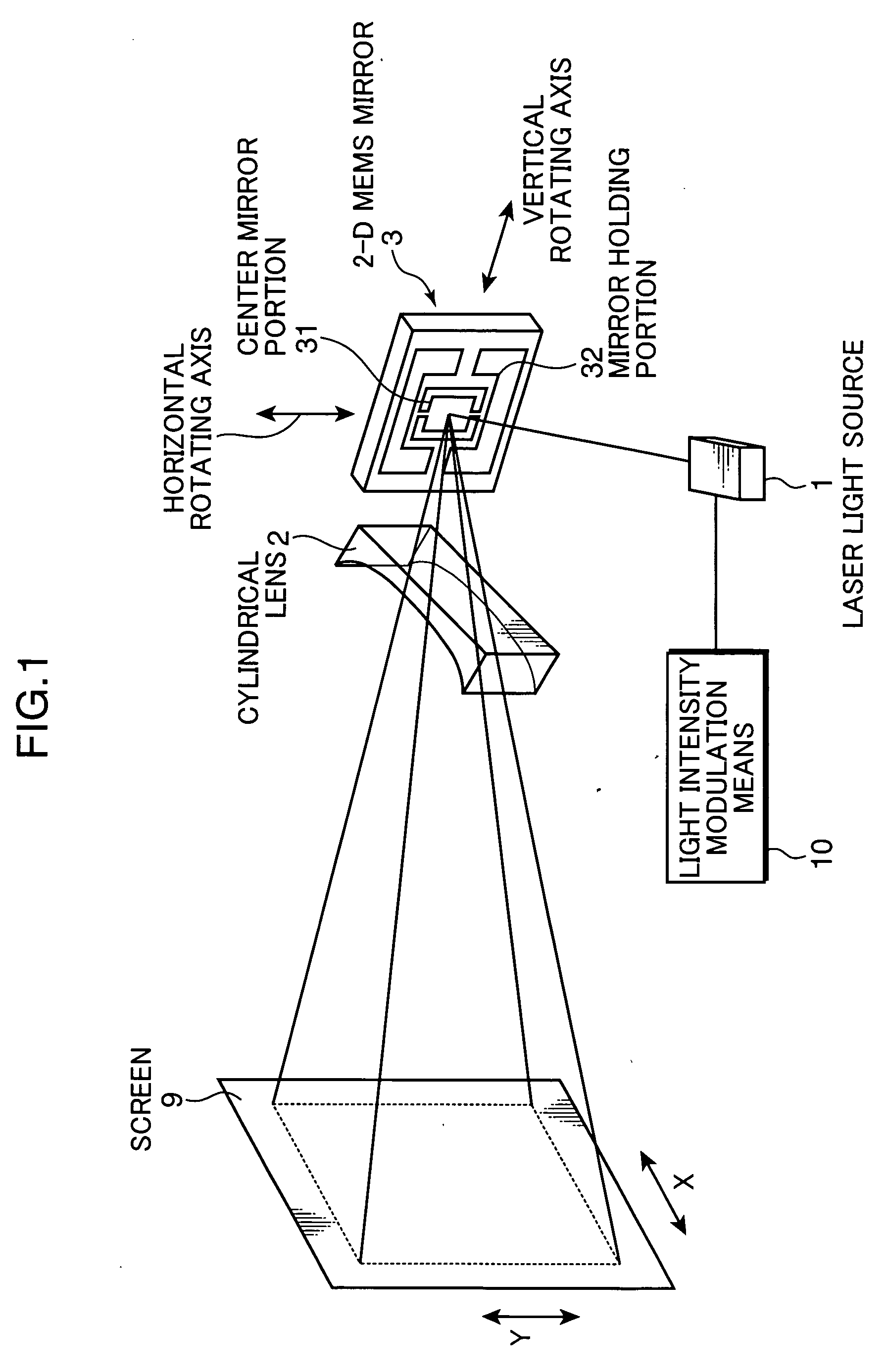
[0021]FIG. 1 is a view schematically showing the configuration of a 2-D image display device of the invention. Light from a laser light source 1, which is modulated in intensity by light intensity modulation means 10 according to an input video signal, irradiates a 2-D MEMS mirror 3. The 2-D MEMS mirror 3 is a movable mirror made of silicon crystal having a thickness of about 10 μm. It is held at a position afloat from the bottom surface substrate by the etching technique. A center mirror portion 31 is connected to mirror holding portions 32 in the vertical direction by means of beams. Also, the mirror holding portions 32 are supported on beams in the horizontal direction. Under the center mirror portion 31, electrodes partitioned to right and left portions are formed on the bottom surface substrate. By applying a voltage between the center mirror portion 31 and the electrodes on t...

second embodiment

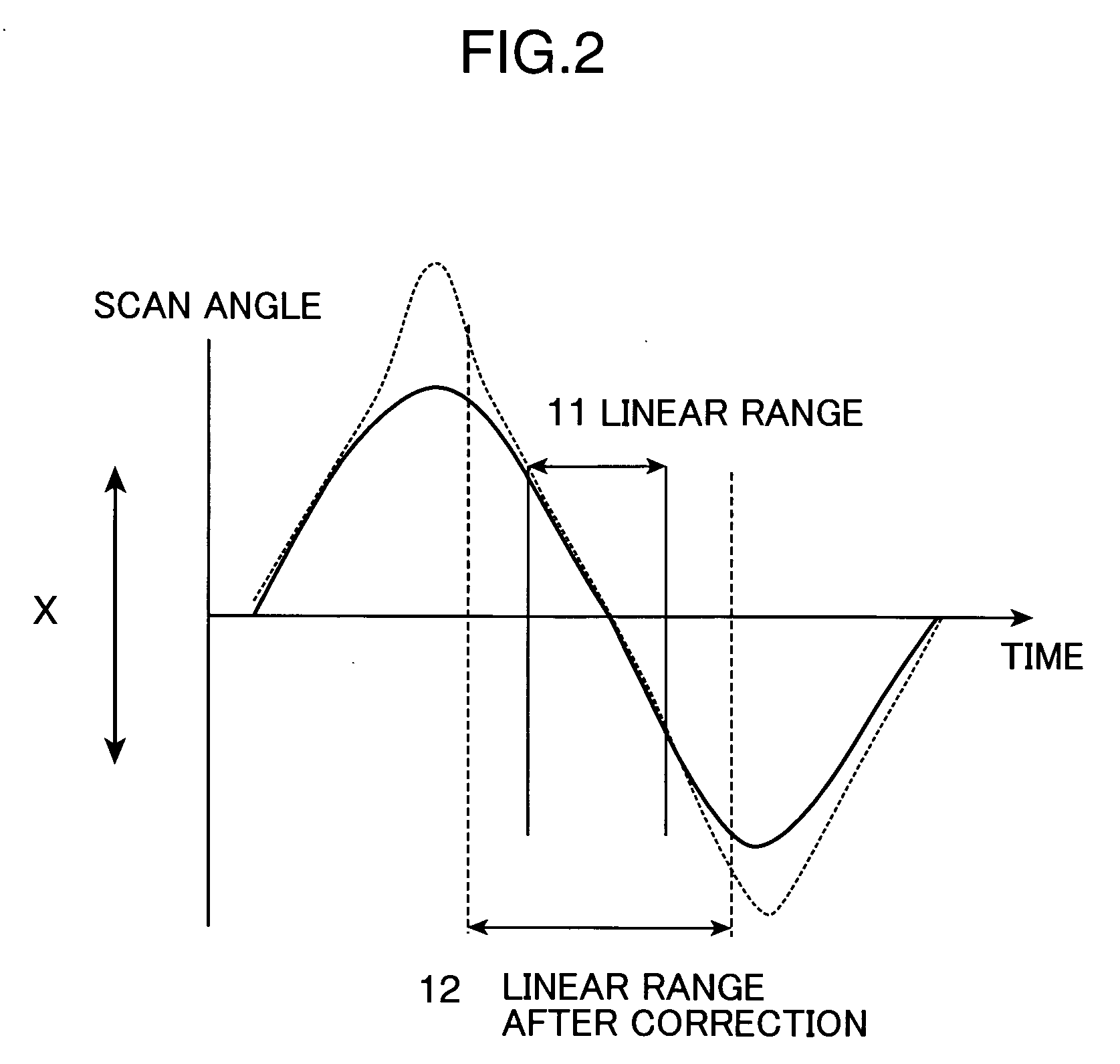
[0037]FIG. 5 shows another embodiment of the correction optical system used in the invention. FIG. 5 shows the optical configuration of the optical system in FIG. 1 in a direction corresponding to the X-direction. Herein, a free-form mirror (one embodiment of the correction optical system) 5 is used as the scan angle correction optical system. The free-form mirror 5 has a concave surface shape at the center, that is, a region where the beam scan angle is small, and a convex surface shape in the peripheral portion, that is, a region where the beam scan angle is large. The scan angle increases rapidly when a beam passes by the peripheral portion of the free-form mirror 5. It is thus possible to suppress the brightness distribution caused by a difference of the scan rates.

[0038] Also, the light shield means as described above can be also provided to the free-form mirror 5. In this case, for example, metal or other materials (carbon black or the like) may be directly formed on the surf...

third embodiment

[0039]FIG. 6 shows one embodiment when a 2-D image display device is constructed from a combination of the illumination light source of the invention and a projection optical system. In the configuration of the second embodiment, an image is formed directly on the screen by scanning light from the laser light source 1 two-dimensionally while modulating the light in intensity. On the contrary, in this embodiment shown in FIG. 6, the laser light source 1 is illuminated at a constant quantity of light, and a spatial light modulation element 6 is illuminated using the 2-D MEMS mirror 3 and a scan angle correction optical system 4. For example, a liquid crystal panel in which optical switches using TN liquid crystal elements are aligned two-dimensionally in multiple arrays is used as the spatial light modulation element 6. The spatial light modulation element 6 is illuminated with a uniform brightness distribution, and a 2-D image formed by passing through the spatial light modulation el...


PUM


Abstract

A 2-D beam scan method using a galvanometer mirror and a polygon scanner has a problem that the polygon scanner is large and noises are increased. Also, a method of oscillating a compact mirror has a problem that a brightness distribution is produced depending on a scan angle. Hence, a beam is scanned while a relatively small mirror, such as an MEMS mirror, is oscillated at or in the vicinity of the resonance frequency. In this instance, the scan angle is corrected with the use of a correction optical system for uniform illumination to be achieved.

Description

TECHNICAL FIELD [0001] The present invention relates to a video projector using a 2-D spatial light modulation element, such as a liquid crystal panel and a DMD. BACKGROUND ART [0002]FIG. 7 is a view schematically showing the configuration of a laser display in the related art described in detail, for example, in Non-Patent Document 1. Light beams from laser light sources 100a through c for three colors, RGB, are combined by dichroic mirrors 102a and 102b, and scanned in the horizontal direction (X-direction) by a polygon scanner 104 and in the vertical direction (Y-direction) by a galvanometer scanner 105 to be irradiated onto a screen 108. In this instance, a video is displayed on the screen 108 by modulating intensity by light modulators 106a through 106c according to an input video signal. For example, in order to display a moving image corresponding to an NTSC video signal, about 500 scan lines in the horizontal direction are displayed for 30 frames per second, and the number o...

Claims


Application Information

Patent Timeline
Patent Type & Authority Applications(United States)
IPC IPC(8): G03B21/26G02B26/10G03B21/28H04N9/31
CPCG02B26/101H04N9/3129G03B21/28
Inventor KASAZUMI, KEN'ICHIMIZUUCHI, KIMINORIYAMAMOTO, KAZUHISA
Owner PANASONIC CORP
Why Eureka
Try Eureka