Projection lens and projection-type display apparatus using the lens
- Summary
- Abstract
- Description
- Claims
- Application Information
AI Technical Summary
Benefits of technology
Problems solved by technology
Method used
Image
Examples
first embodiment
[0099]A projection lens according to the first embodiment of the present invention is designed to achieve excellent projection performance, while reducing the size of the projection lens (compact projection lens).
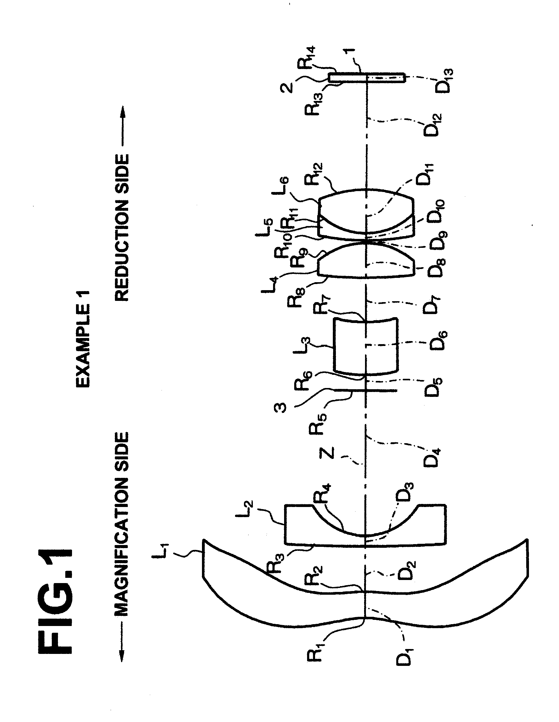
[0100]As illustrated in FIG. 1, the projection lens according to the first embodiment includes first lens L1 having at least an aspheric surface, second lens L2 having a concave surface facing the reduction side of the projection lens, and having negative refractive power, third lens L3, fourth lens L4 having a convex surface facing the reduction side, and having positive refractive power, fifth lens L5 having a concave surface facing the reduction side, and having negative refractive power, and sixth lens L6 having a convex surface facing the reduction side, and having positive refractive power, which are sequentially arranged from the magnification side of the projection lens. Further, the reduction side of the projection lens is telecentric. Further, a stop (a mask may b...
second embodiment
[0133]A projection lens according to the second embodiment is designed in such a manner to have excellent projection performance, while reducing the size of the projection lens.
[0134]Specifically, as illustrated in FIG. 7, the projection lens according to the second embodiment includes first lens L1 having at least an aspheric surface, second lens L2 having a concave surface facing the reduction side of the projection lens, and having negative refractive power, third lens L3 having positive refractive power, fourth lens L4 having negative refractive power, fifth lens L5 having positive refractive power, sixth lens L6 having a convex surface facing the reduction side, and having positive refractive power, seventh lens L7 having a concave surface facing the reduction side, and having negative refractive power, and eighth lens L8 having a convex surface facing the reduction side, and having positive refractive power, which are sequentially arranged from the magnification side of the pr...
example 1
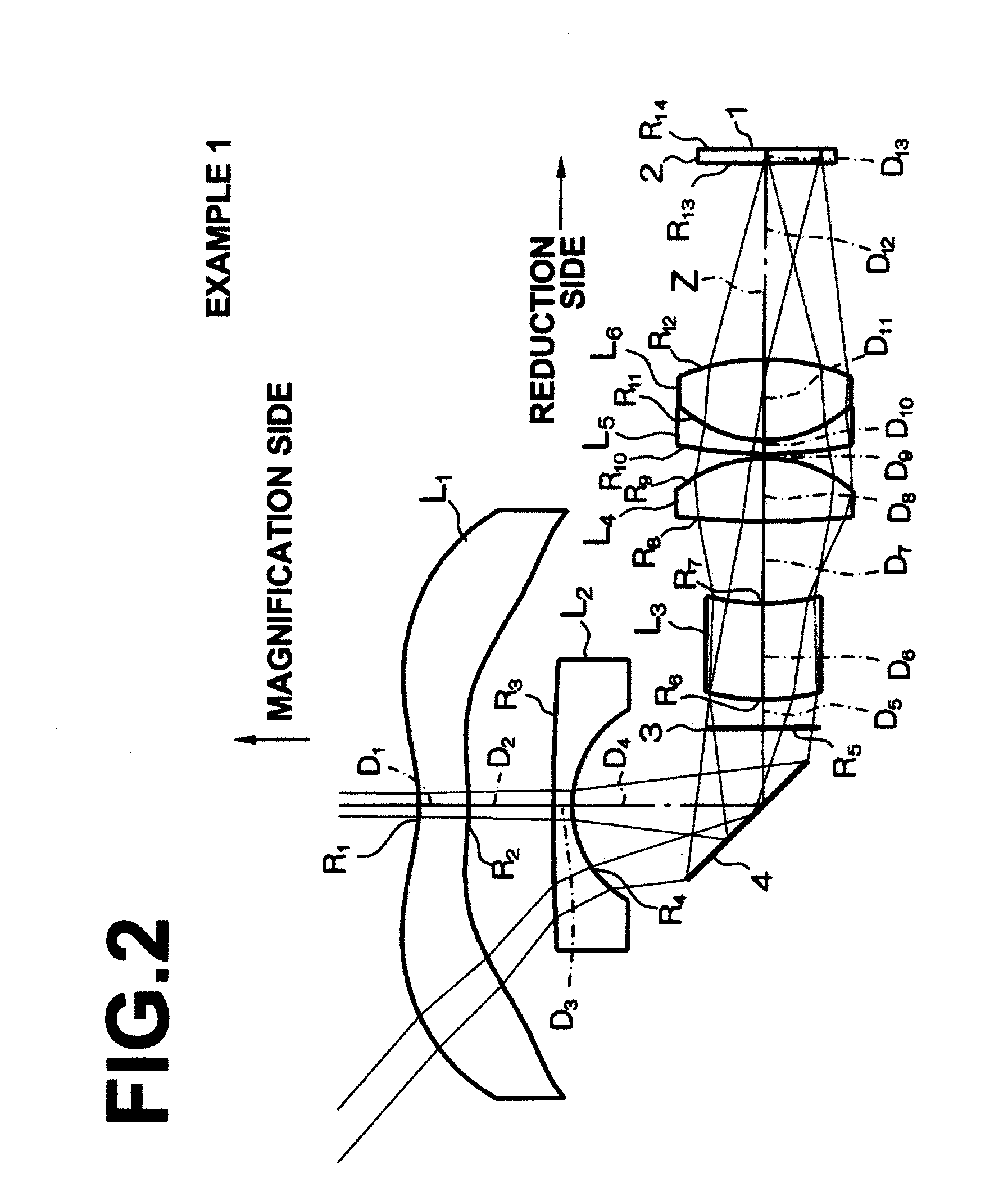
[0172]As illustrated in FIG. 1, a projection lens in Example 1 includes six lenses L1 through L6, which are sequentially arranged from the magnification side of the projection lens, and an aperture stop (a mask may be provided instead of the aperture stop) 3. Further, the reduction side of the projection lens is substantially telecentric. FIG. 2 is a diagram illustrating a case of arranging a light reflection mirror, as the light deflection means 4 for deflecting light, between the second lens L2 and the third lens L3 in the projection lens illustrated in FIG. 1.
[0173]Specifically, first lens L1, second lens L2, an aperture stop (a mask may be provided instead of the aperture stop) 3, third lens L3, fourth lens L4, fifth lens L5, and sixth lens L6 are sequentially arranged from the magnification side of the projection lens. The first lens L1 has small refractive power, and both surfaces of the first lens L1 are aspheric. The second lens L2 is a negative meniscus lens having a concav...
PUM
 Abstract
Description
Claims
Application Information
 - R&D
- Intellectual Property
- Life Sciences
- Materials
- Tech Scout
- Unparalleled Data Quality
- Higher Quality Content
- 60% Fewer Hallucinations
Browse by: Latest US Patents, China's latest patents, Technical Efficacy Thesaurus, Application Domain, Technology Topic, Popular Technical Reports.
© 2025 PatSnap. All rights reserved.Legal|Privacy policy|Modern Slavery Act Transparency Statement|Sitemap|About US| Contact US: help@patsnap.com


