Circuit and method for coupling electrical energy to a resonated inductive load

a technology of electrical energy and inductive load, applied in the direction of electric variable regulation, process and machine control, instruments, etc., can solve the problem of reducing the efficiency of circuit energy transfer

Inactive Publication Date: 2011-10-06
RES LIMITED
View PDF3 Cites 34 Cited by
  • Summary
  • Abstract
  • Description
  • Claims
  • Application Information

AI Technical Summary

Benefits of technology

[0048]The energy transfer capacitance, the resonating capacitance and the inductive load device may be effectively connected together in parallel while performing Steps 3 and 4.
[0049]The energy transfer capacitance, the resonating capacitance and the inductive load device may be effectively connected together in a series circuit while performing Steps 3 and 4.

Problems solved by technology

However, the circuit energy transfer efficiencies decrease as the distance between the inductively coupled or linked inductive components increases.

Method used


Image

  • Circuit and method for coupling electrical energy to a resonated inductive load
  • Circuit and method for coupling electrical energy to a resonated inductive load
  • Circuit and method for coupling electrical energy to a resonated inductive load

Examples


first embodiment

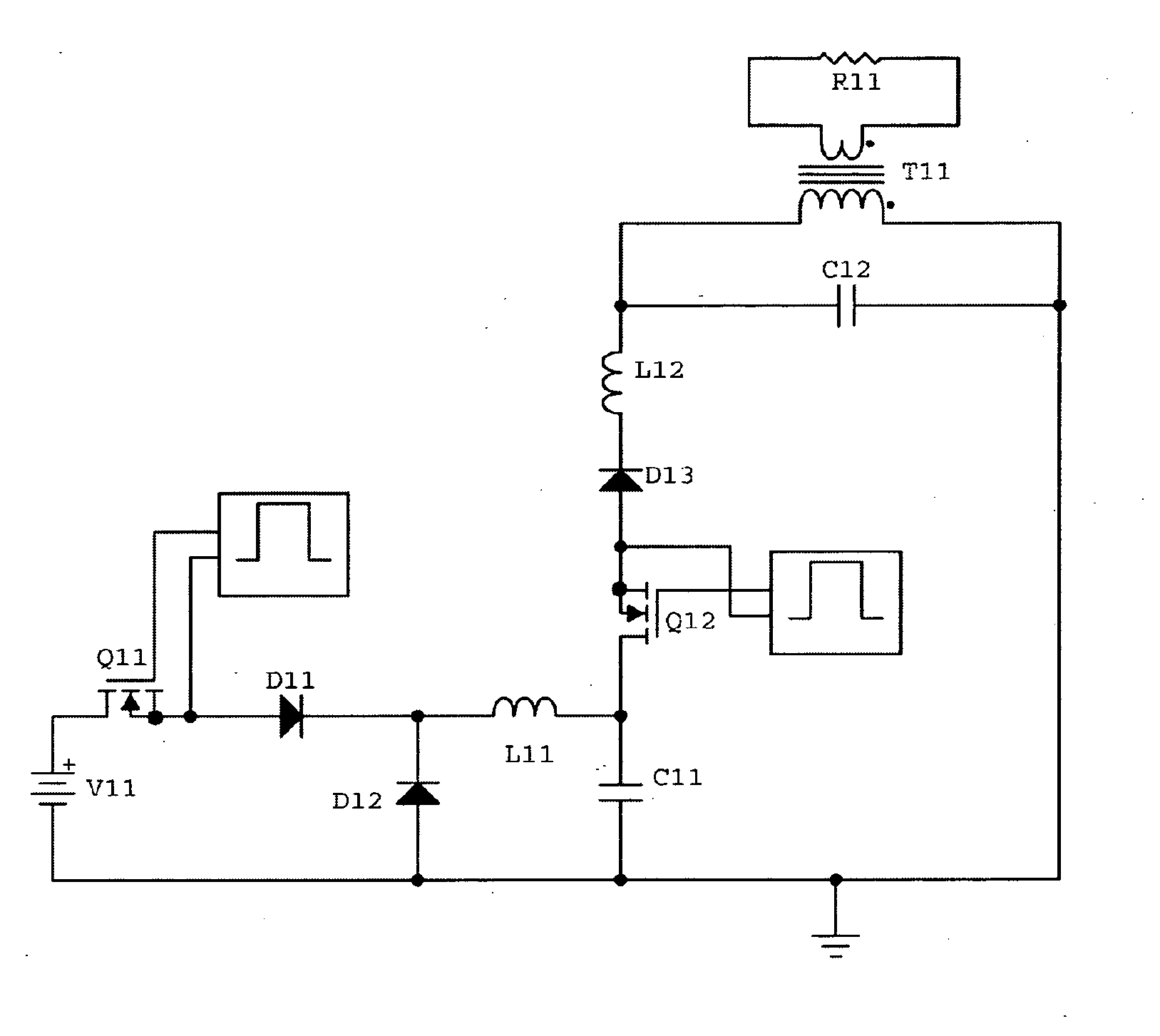
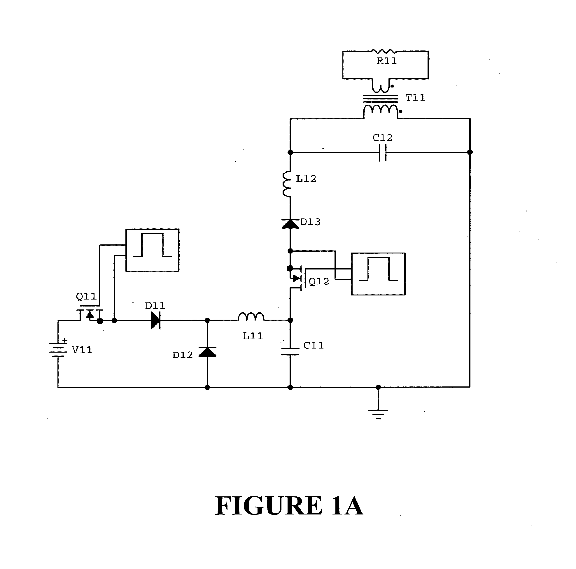
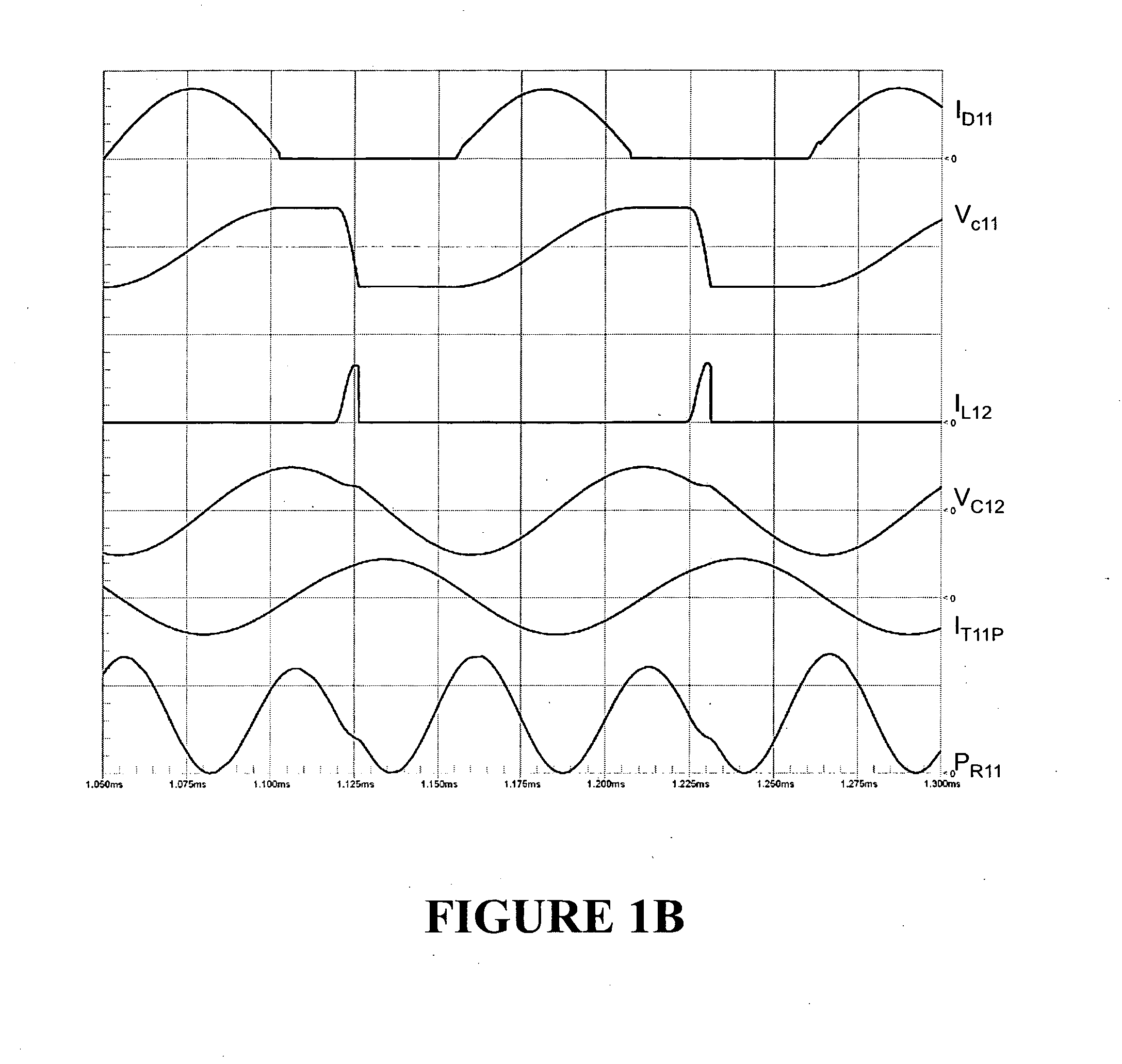
[0202]FIG. 1A shows a circuit and FIGS. 1B and 1C show two sets of waveforms, for two specific versions of a first embodiment of the invention. This circuit injects unidirectional current pulses into a parallel resonated load circuit formed by a resonating capacitor C12 connected to an inductive load device. The inductive load device is a work coil of an induction heating system and is represented in FIG. 1A by the primary winding of a loosely coupled transformer T11. The resonating capacitor C12 is continuously connected in parallel with the transformer primary winding. A low resistance load resistor R11 is connected across the transformer secondary winding to represent the work piece of the induction heating system. A DC supply of electrical energy V11 is coupled to the resonated load circuit by a switched coupling circuit.

[0203]As shown in FIG. 1A, the switched coupling circuit includes a charging control transistor Q11, series blocking diode D11, a free-wheel diode D12, a series...

second embodiment

[0255]FIGS. 2A and 2B show a circuit and waveforms for a second embodiment of the invention. This circuit injects unidirectional current pulses into a series resonated load circuit formed by a resonating capacitor C22 connected in series with an inductive load device. The inductive load device is a work coil of an induction heating system and is represented in FIG. 2A by the primary winding of a loosely coupled transformer T21. The resonating capacitor C22 is continuously connected in series with the transformer primary winding. A low resistance load resistor R21 is connected across the transformer secondary winding to represent the work piece of the induction heating system. A DC supply of electrical energy V21 is coupled to the resonated load circuit by a switched coupling circuit.

[0256]A load circuit control transistor Q23 controls the opening and closing of the series resonated load circuit. Oscillating load circuit currents can circulate in one direction (anti-clockwise in FIG....

third embodiment

[0299]FIGS. 3A and 3B show a circuit and waveforms for a third embodiment of the invention. This circuit injects unidirectional current pulses into the inductive leg of a resonated load circuit formed by a resonating capacitor C32 connected to an inductive load device. The inductive load device is a work coil of an induction heating system and is represented in FIG. 3A by the primary winding of a loosely coupled transformer T31. One end of the resonating capacitor C32 is continuously connected to one end of the primary winding of the transformer T31. A low resistance load resistor R11 is connected across the transformer secondary winding to represent the work piece of the induction heating system. A DC supply of electrical energy V31 is coupled to the resonated load circuit by a switched coupling circuit.

[0300]This third embodiment circuit of FIG. 3A operates similarly to the second embodiment circuit of FIG. 2A as described above, with the exception of the injection of current and ...


PUM


Abstract

A switching circuit (Q11, Q12, D11, D12, D13, L11, L12) is repetitively configured to charge an energy transfer capacitance (C11) from an electrical supply (V11) and then inject a discrete pulse of energy into a resonated load circuit by dis charging the capacitance. The load circuit is formed by a resonating capacitance (C12) and an inductive load device (T11, R11), eg motor, or induction heating or power transfer device. Energy circulates in the load circuit at or near to its natural resonant frequency. There is no injection of energy into the load circuit while energy for charging the transfer capacitance is being delivered from the supply to the switching circuit. During injection, the two capacitances and the inductive load device may be connected together in parallel or in series, or the transfer capacitance may be connected in series with the inductive load device but not the resonating capacitor.

Description

FIELD OF INVENTION[0001]The present invention relates to electrical circuits for powering inductive loads. More particularly, the present invention relates to a circuit for coupling a supply of electrical energy to an inductive load device that is resonated with a capacitance. Examples of specific applications of the present invention include driving low to medium frequency induction heating and inductive power transfer devices, or alternating current motors running in resonant mode, for example induction or synchronous reluctance.BACKGROUND[0002]Resonant circuits are used in many electrical devices where it is desired to inductively transfer energy across an air gap, for example in induction heaters or cooktops, induction heat treatment, induction furnaces and inductive power transfer devices such as those used for charging batteries or other energy storage devices in electric vehicles, cell phones, portable computers, or other rechargeable appliances. Resonant circuits are also us...

Claims


Application Information

Patent Timeline
Patent Type & Authority Applications(United States)
IPC IPC(8): H02M7/537
CPCH02M7/537Y02B70/1441H05B6/06H02M2007/4815H02M7/4815Y02B70/10
Inventor GRAY, ASHLEY JAMESILLSLEY, NEVILLE ROY SAMUEL
Owner RES LIMITED
Why Eureka
Try Eureka