Diffraction grating and alignment method thereof, and radiation imaging system

a radiation imaging system and alignment method technology, applied in the field of diffraction grating and alignment method thereof, can solve the problems of degradation of image quality of phase contrast image, insufficient contrast of x-ray absorption image of living soft tissue, soft material, etc., and achieve high degree of accuracy and high image quality

Inactive Publication Date: 2011-10-06
FUJIFILM CORP
View PDF2 Cites 68 Cited by
  • Summary
  • Abstract
  • Description
  • Claims
  • Application Information

AI Technical Summary

Benefits of technology

[0023]According to the present invention, the position and angle of the plural diffraction gratings can be precisely adjusted based on the dose of the passing X-rays and the moiré pattern, which are measurable without use of a measuring instrument with high degree of accuracy, and hen

Problems solved by technology

Thus, the X-ray absorption image of living soft tissue, soft material, or the like cannot have sufficient contrast.
Thus, the X-ray absorption image of the arthrosis hardly has sufficient contrast.
If the focus size of the X-ray source is large, the self image of the first diffraction grating is blurred, and the blur causes degradation in image quality of the phase contrast image.
Especially, it is expected that a relat

Method used


Image

  • Diffraction grating and alignment method thereof, and radiation imaging system
  • Diffraction grating and alignment method thereof, and radiation imaging system
  • Diffraction grating and alignment method thereof, and radiation imaging system

Examples


first embodiment

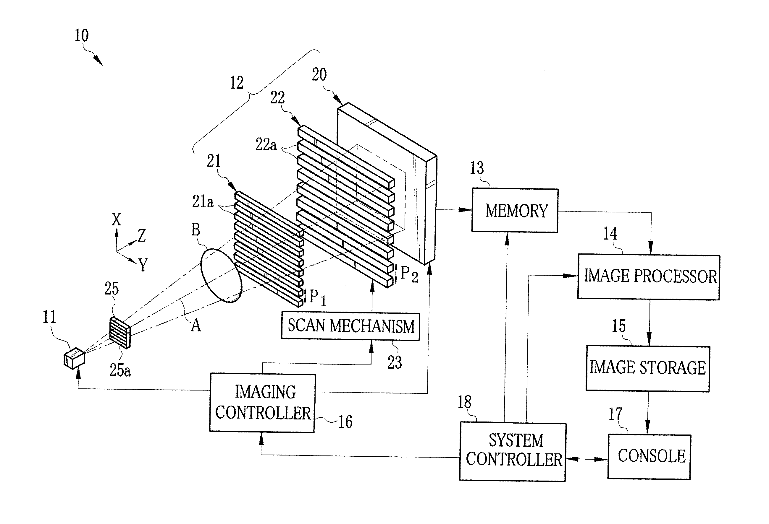
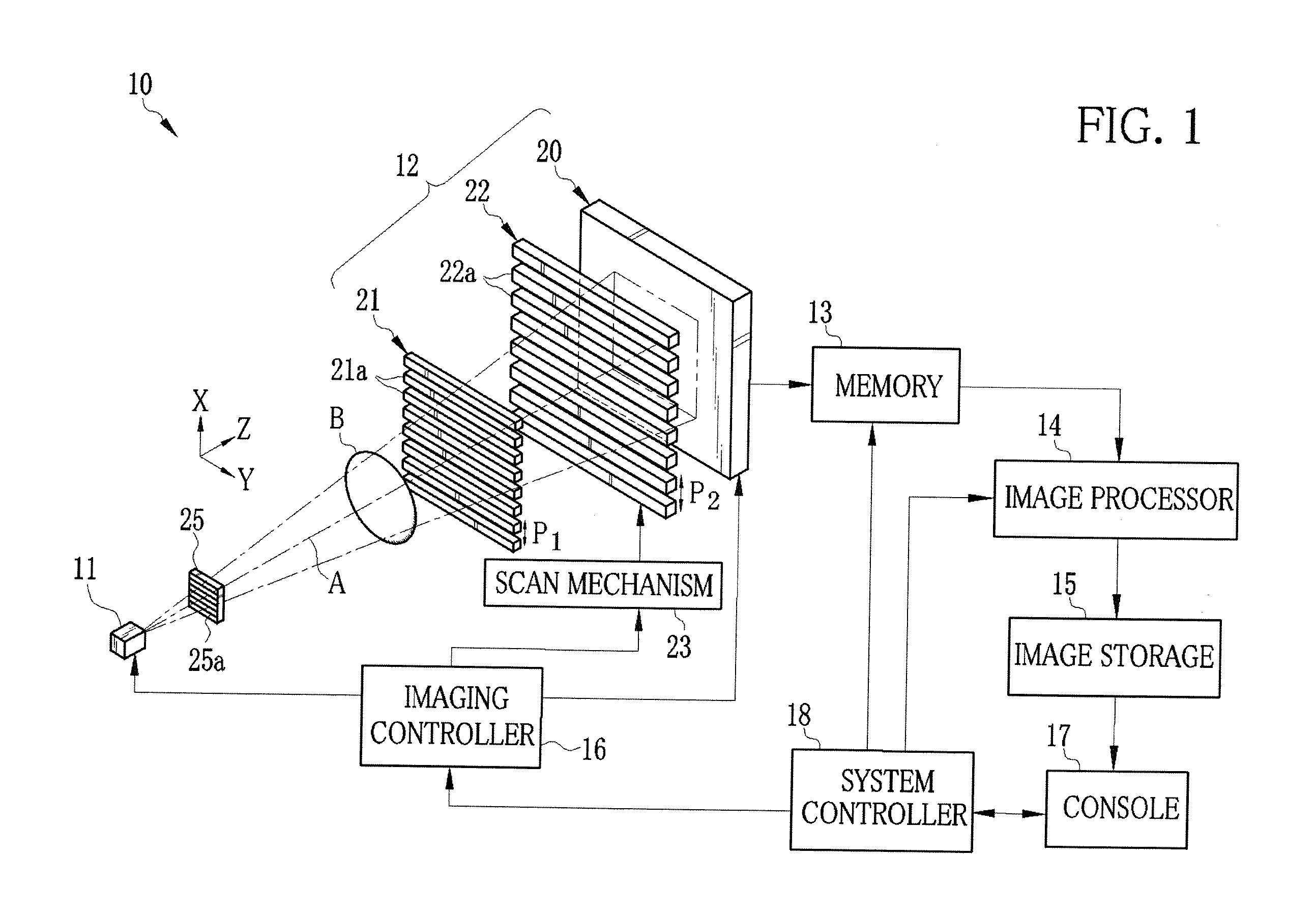
[0042]As shown in FIG. 1, an X-ray imaging system 10 according to a first embodiment is constituted of an X-ray source 11 for applying X-rays to an object B, an imaging unit 12 disposed so as to face the X-ray source 11, a memory 13, an image processor 14, an image storage 15, an imaging controller 16, a console 17 including an operation unit and a monitor, and a system controller 18. The imaging unit 12 detects the X-rays that have been emitted from the X-ray source 11 and passed through the object B, to produce image data. The memory 13 stores the image data outputted from the imaging unit 12. The image processor 14 produces a phase contrast image from plural frames of image data stored on the memory 13. The image storage 15 stores the phase contrast image produced by the image processor 14. The imaging controller 16 controls the X-ray source 11 and the imaging unit 12. The system controller 18 carries out centralized control of the entire X-ray imaging system 10 based on an opera...

second embodiment

[0098]In a second embodiment, the grating has an alignment section for use in the position adjustment. The same reference numerals as those of the first embodiment refer to the same or similar components, and detailed description thereof will be omitted. As shown in FIG. 12, in an X-ray imaging system 60 according to the second embodiment, the second absorption grating 22 is provided with alignment sections 61a to 61d at each of four corners unused in the imaging. As shown in FIG. 13, the alignment section 61a has four areas divided along the X and Y axes passing through the center of the alignment section 61a, and first to fourth alignment patterns 62 to 65 are provided in the four areas. Also, a fifth alignment pattern 66 is provided in a middle area of the alignment section 61a. Since the alignment areas 61b to 61d are the same as the alignment area 61a, the detailed description thereof is omitted.

[0099]Each of the first to fifth alignment patterns 62 to 66 is a grid pattern. A g...


PUM


Abstract

An X-ray imaging system includes first to third absorption gratings. Initially, the third absorption grating is disposed in a Z axis orthogonal to a detection surface of a FPD, and the position of the third absorption grating is adjusted in θx and θy directions based on a dose of X-rays having passed through the third absorption grating. Then, the first absorption grating is disposed in the Z axis so as to produce a moiré pattern. The position of the first absorption grating is adjusted in the θx and θy directions so that a frequency of the moiré pattern detected by the FPD becomes uniform. Then, the position of the first absorption grating is adjusted in a Z or θz direction so that the FPD loses the detection of the moiré pattern. After that, the second absorption grating is aligned in a like manner as the first absorption grating.

Description

BACKGROUND OF THE INVENTION[0001]1. Field of the Invention[0002]The present invention relates to an alignment method of plural diffraction gratings, and the diffraction gratings that are easy to align, in a radiation imaging system for capturing a phase contrast image of an object with use of the diffraction gratings.[0003]2. Description Related to the Prior Art[0004]X-rays are used as a probe for imaging inside of an object without incision, due to the characteristic that attenuation of the X-rays depends on the atomic number of an element constituting the object and the density and thickness of the object. Radiography using the X-rays is widely available in fields of medical diagnosis, nondestructive inspection, and the like.[0005]In a conventional X-ray imaging system for capturing a radiographic image of the object, the object to be examined is disposed between an X-ray source for emitting the X-rays and an X-ray image detector for detecting the X-rays. The X-rays emitted from t...

Claims


Application Information

Patent Timeline
IPC IPC(8): G01N23/04
CPCA61B6/06A61B6/4233A61B6/484G01N23/04A61B6/4291G21K1/025G21K1/06G21K2207/005A61B6/4021G01N2223/1016G01N23/041
Inventor KANEKO, YASUHISAISHII, HIROYASU
Owner FUJIFILM CORP
Why Eureka
Try Eureka