
Flywheel device

a technology of flywheel and rotor, which is applied in the direction of vibration suppression adjustment, yielding coupling, spring/damper, etc., can solve the problems of reducing the mass productivities of components, disadvantageous in terms of costs, and reducing production costs, so as to facilitate the increase of the mass of the mass ring

Inactive Publication Date: 2011-10-06
YUTAKA GIKEN CO LTD
View PDF3 Cites 5 Cited by
  • Summary
  • Abstract
  • Description
  • Claims
  • Application Information

AI Technical Summary

Benefits of technology

[0006]The present invention has been made in view of such circumstances, and an object of the present invention is to provide a structurally simple and inexpensive flywheel device which enables coaxial positioning of a mass-side rotor and a drive plate with respect to each other without performing burdensome machining on a mass ring for forming a positioning apparatus, and which facilitates increasing the mass of the mass ring along with change in specifications.
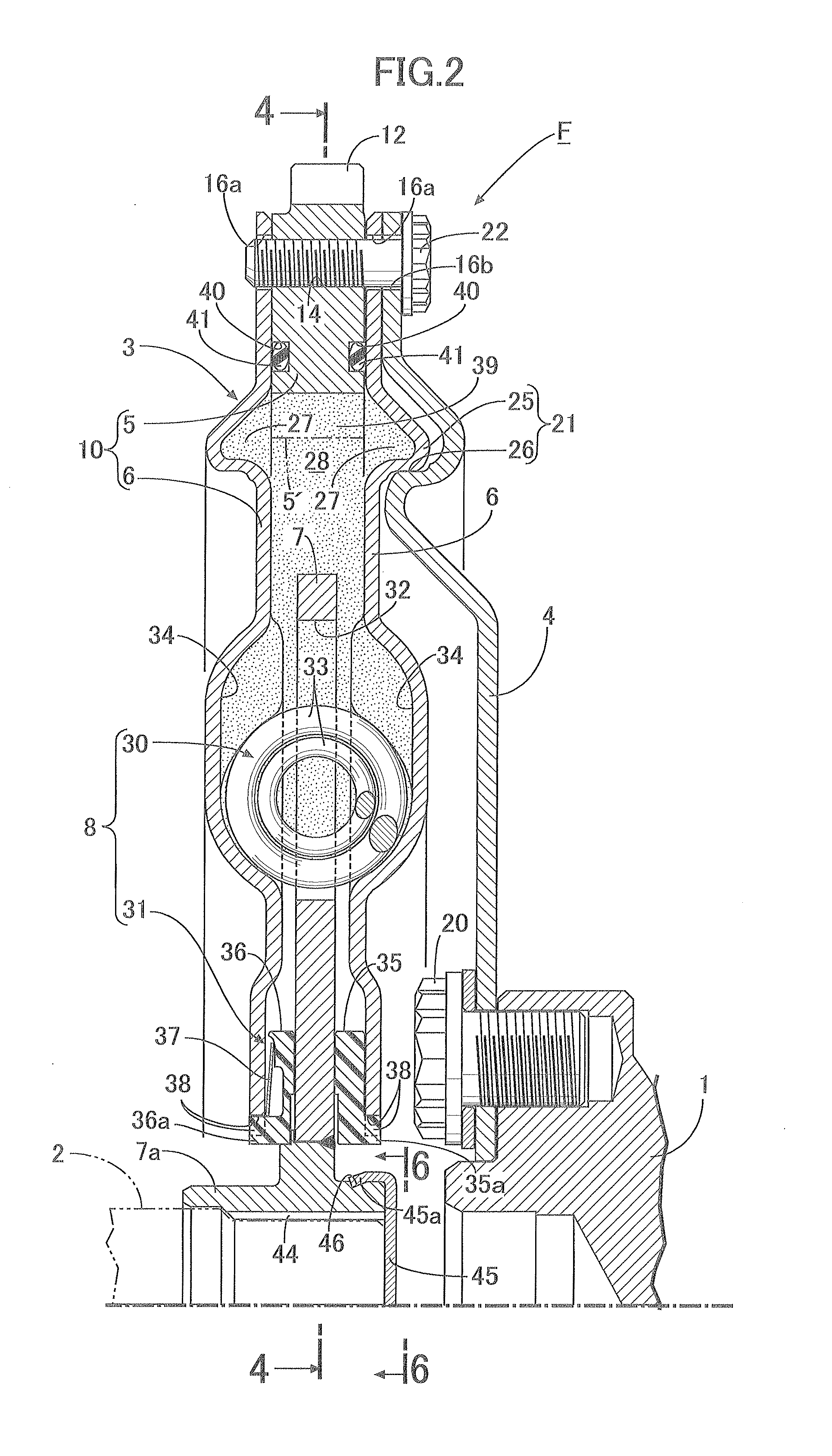
[0008]According to the first feature of the present invention, the annular positioning protrusion and the positioning recessed portion, which are fitted to each other and constitute the positioning apparatus, are press formed respectively in the holder plate and the drive plate facing each other. Accordingly, the mass ring held between the holder plates can have flat- and simple-shaped side surfaces. In addition, it is not necessary to perform burdensome cutting on, of course, the mass ring, nor the holder plates, which enables reduction in production costs.
[0010]According to the second feature of the present invention, the positioning protrusion is formed in each of the pair of holder plates. Accordingly, any one of the holder plates can be positioned relative to and connected to the drive plate, so that the concern about misassembly can be eliminated. Moreover, the inner peripheral end of the mass ring faces the annular recessed portions which correspond to the positioning protrusions and which are formed on the inner side surfaces of the holder plates, and the driven plate is disposed inward of the annular recessed portions in the radial direction, thereby allowing the mass of the mass ring to be increased on the inner peripheral side. Accordingly, when the mass of the mass ring needs to be increased along with change in specification of the flywheel device, it is only necessary to replace the mass ring with one having a smaller inner diameter, so that the need for change in shape or structure of the holder plates is eliminated. This allows change in specification of the flywheel device at low costs.
[0012]According to the third feature of the present invention, the holder plates can be constituted by disposing two holder plates of the same shape with each positioning protrusion facing outward. Accordingly, the mass productivity of the holder plates is improved, which can contribute to cost reduction.
[0014]According to the forth feature of the present invention, the multiple rivets and bolts are arranged on the same circumference. Accordingly, rivet holes and screw holes for the rivets and bolts can be easily formed in the holder plates and the mass ring on the same circumference, which leads to a good processability. Moreover, the relief holes for receiving the enlarged end portions of the rivets are provided in the drive plate. Accordingly, the drive plate can come into close contact with the holder plate, without being interfered with the rivets.

Problems solved by technology

However, since the mass ring is generally forged or cast, the formation of the positioning protrusion or the positioning recessed portion therein requires a complicated forming die or cutting after the forging or casting, each of which is a factor inhibiting the reduction in production costs.
As a result, the mass productivities of components are reduced, which is also disadvantageous in terms of costs.

Method used


Image

  • Flywheel device
  • Flywheel device
  • Flywheel device

Examples


Embodiment Construction

[0023]An embodiment of the present invention will be described below based on the attached drawings.

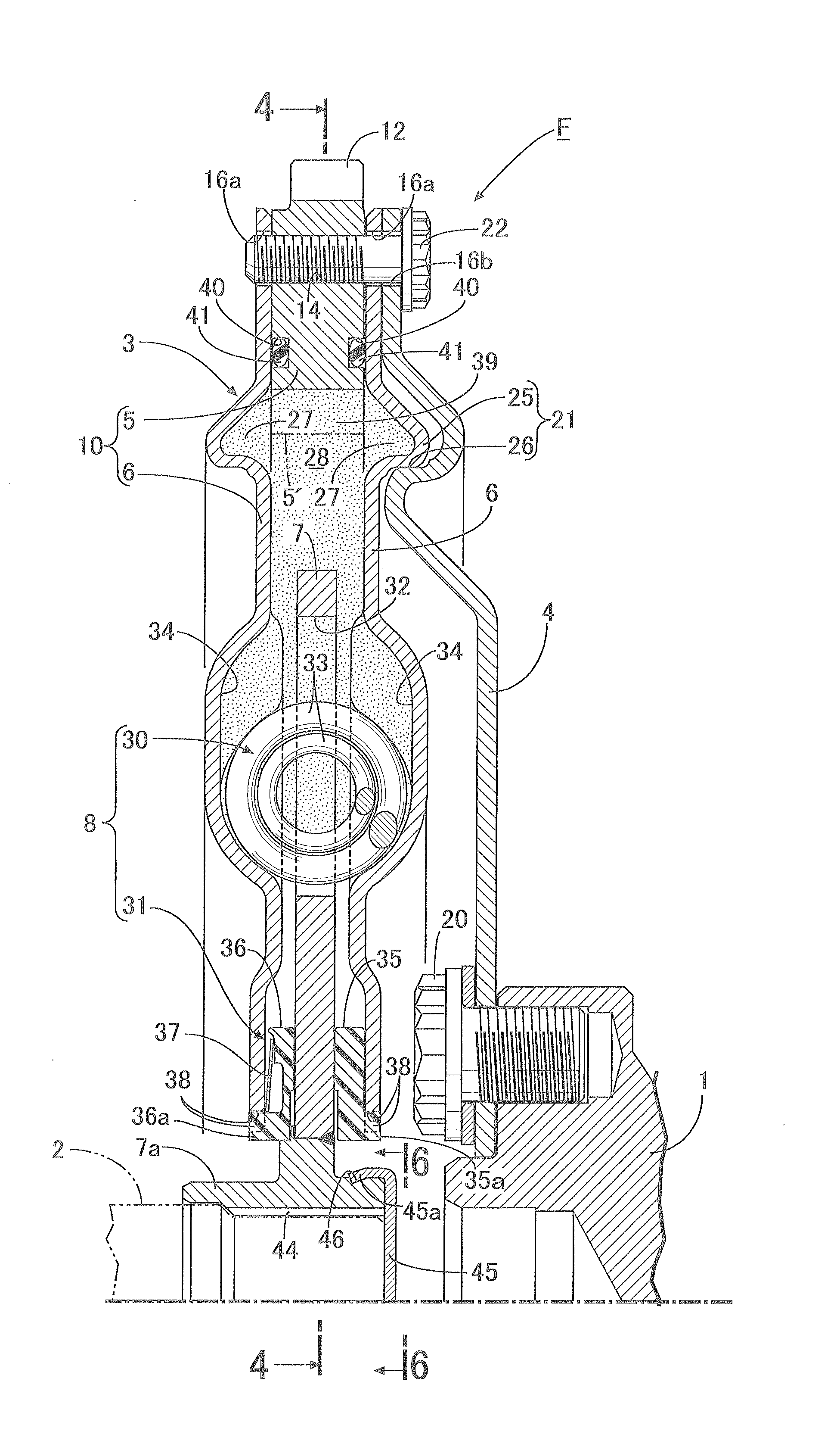
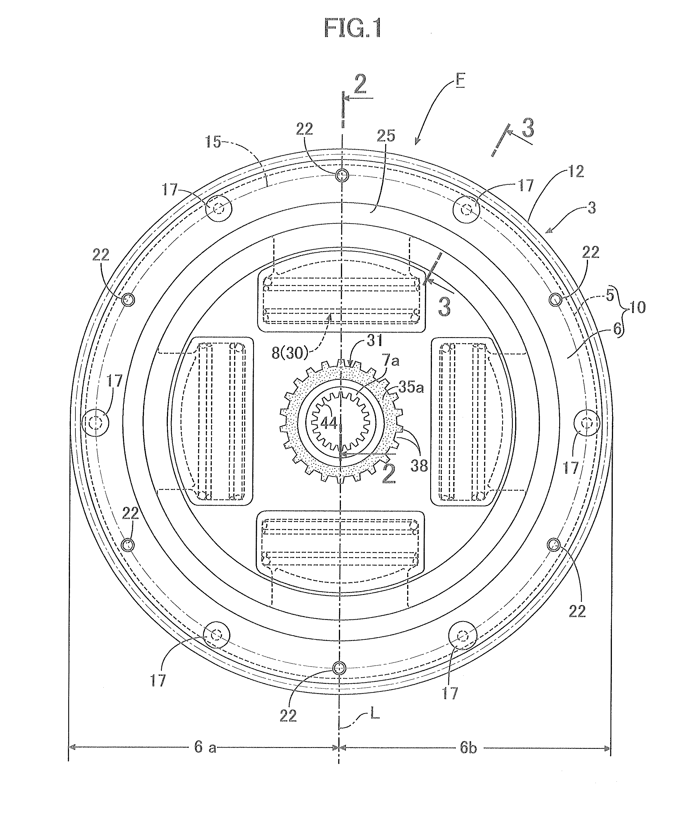
[0024]In FIGS. 1 to 3 and 7, power from a crankshaft 1 of an engine is transmitted through a flywheel device F of the present invention to an output shaft 2 continuing to a clutch or a transmission. The flywheel device F includes a flywheel assembly 3 and a drive plate 4 connecting the flywheel assembly 3 to the crankshaft 1.

[0025]The flywheel assembly 3 includes a mass ring 5, a pair of holder plates 6, 6, a driven plate 7, and a torque damper 8. The holder plates 6, 6 have their outer peripheral portions connected to the mass ring 5 with the mass ring 5 sandwiched therebetween. The driven plate 7 includes an output hub 7a disposed coaxially with the mass ring 5 and is disposed between the holder plates 6, 6 rotatably relative to holder plates 6, 6. The torque damper 8 is interposed between the holder plates 6, 6 and the driven plate 7. In addition, the mass ring 5 and both the holde...


PUM


Abstract

A flywheel device includes a mass-side rotor including a mass ring and a pair of holder plates connected to both sides of the mass ring. The mass-side rotor is connected to a crankshaft with a drive plate therebetween. Between the mass-side rotor and the drive plate, a positioning apparatus for positioning those coaxially with each other is provided. The positioning apparatus includes: an annular positioning protrusion which is press formed in at least one of the pair of holder plates to project laterally outward therefrom, and which is disposed coaxially with the mass-side rotor; and a positioning recessed portion which is press formed in the drive plate coaxially with the crankshaft, and which is fitted to the positioning protrusion. Accordingly, it is possible to enable coaxial positioning of the mass-side rotor and the drive plate without performing burdensome machining on the mass ring for forming a positioning apparatus.

Description

BACKGROUND OF THE INVENTION[0001]1. Field of the Invention[0002]The present invention relates to an improvement of a flywheel device, in which a flywheel assembly includes: a mass-side rotor including a mass ring and a pair of holder plates having outer peripheral portions connected to the mass ring with the mass ring sandwiched therebetween; a driven plate which includes an output hub disposed coaxially with the mass ring and which is disposed between the holder plates rotatably relative to the holder plates; and a torque damper interposed between the holder plates and the driven plate, the mass-side rotor is connected to a crankshaft with a drive plate therebetween, and positioning means for positioning the mass-side rotor and the drive plate coaxially with each other is provided between the mass-side rotor and the drive plate.[0003]2. Description of the Related Art[0004]Such a flywheel device is already known, for example, as disclosed in Japanese Patent Application Laid-open No....

Claims


Application Information

Patent Timeline
Patent Type & Authority Applications(United States)
IPC IPC(8): F16D3/12F16D3/14F16F15/123F16F15/129
CPCF16F15/1203F16F15/1207Y10T74/2132F16F15/13164F16F15/1315
Inventor USUI, ICHIROSAITO, HIROYUKI
Owner YUTAKA GIKEN CO LTD
Learn More