

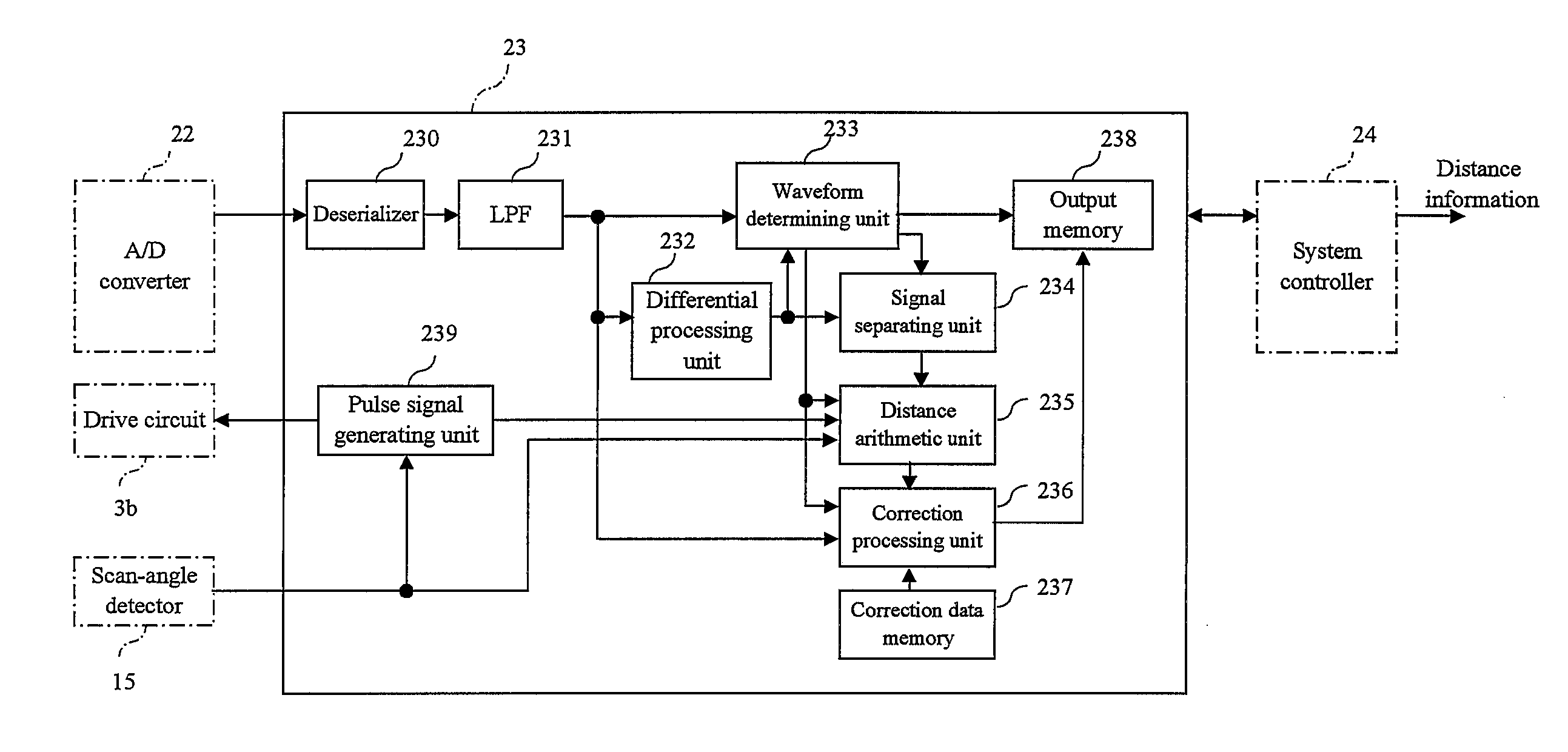
Signal processing apparatus used for operations for range finding and scanning rangefinder
a technology of signal processing apparatus and scanning rangefinder, which is applied in the direction of distance measurement, instruments, and using reradiation, etc., can solve the problems of unclear optical window from which the measurement beam is emitted, contaminated, and inability to accurately calculate etc., to achieve accurate calculation of the distance to the target measured object
- Summary
- Abstract
- Description
- Claims
- Application Information
AI Technical Summary
Benefits of technology
Problems solved by technology
Method used
Image

Examples
Embodiment Construction
[0034]Embodiments of the signal processing apparatus and the scanning rangefinder will be described with reference to the drawings.
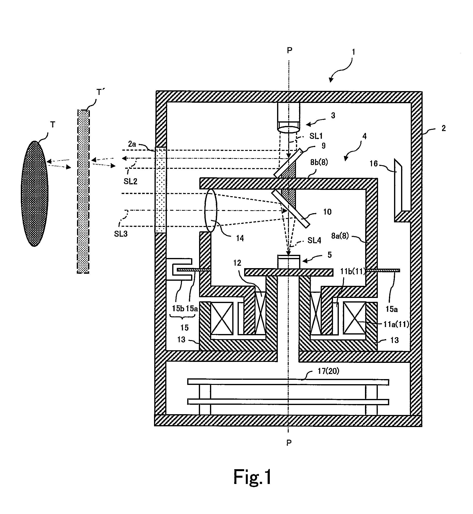
[0035]As shown in FIG. 1, a scanning rangefinder 1 includes a cylindrical casing 2 that accommodates a pair of a light emitting unit 3 and a light receiving unit 5, an arc-shaped optical window 2a disposed along the circumferential direction of the casing 2, and a deflection optical system 4.
[0036]The deflection optical system 4 rotates a first deflection mirror 9 that reflects the measurement beam output from the light emitting unit 3 in a deflected manner in a direction perpendicular to a rotation axis P of the cylindrical casing 2 and rotates, about the rotation axis P, a second deflection mirror 10 that reflects the reflected beam reflected from a measured object in the deflected manner toward the light receiving unit 5, so as to rotatably scan the measurement beam on a surface perpendicular to the rotation axis P.
[0037]The inner-wall surface of the ...
PUM
 Abstract
Description
Claims
Application Information