Manufacture of coil springs

a technology for manufacturing apparatus and coil springs, which is applied in the field of apparatus for the manufacture of coil springs, can solve the problems of increasing the time taken to change the geometry affecting the performance so as to improve the resilience and/or the resistance to fatigue of the coil spring, reduce the arcing, and improve the properties of the coil spring

Active Publication Date: 2011-10-13
SPRINGFORM TECH
View PDF6 Cites 6 Cited by
  • Summary
  • Abstract
  • Description
  • Claims
  • Application Information

AI Technical Summary

Benefits of technology

Furthermore, the first and second tools are preferably adapted to have a substantially consistent quality of electrical contact with the wire, and the materials of the first and second tools are preferably selected to reduce arcing between the tool and the wire.
The apparatus is preferably adapted to heat the wire before, or during, deformation of the wire into a coil spring, such that this deformation occurs whilst the wire has an elevated temperature relative to its surroundings. In particular, the wire preferably has a temperature during deformation into a coil spring that is...

Problems solved by technology

However, conventional methods of manufacturing pocketed coil springs that include a heat treatment step suffer from numerous disadvantages.
This heat treatment step is often the slowest step in the ...

Method used


Image

  • Manufacture of coil springs
  • Manufacture of coil springs
  • Manufacture of coil springs

Examples


first embodiment

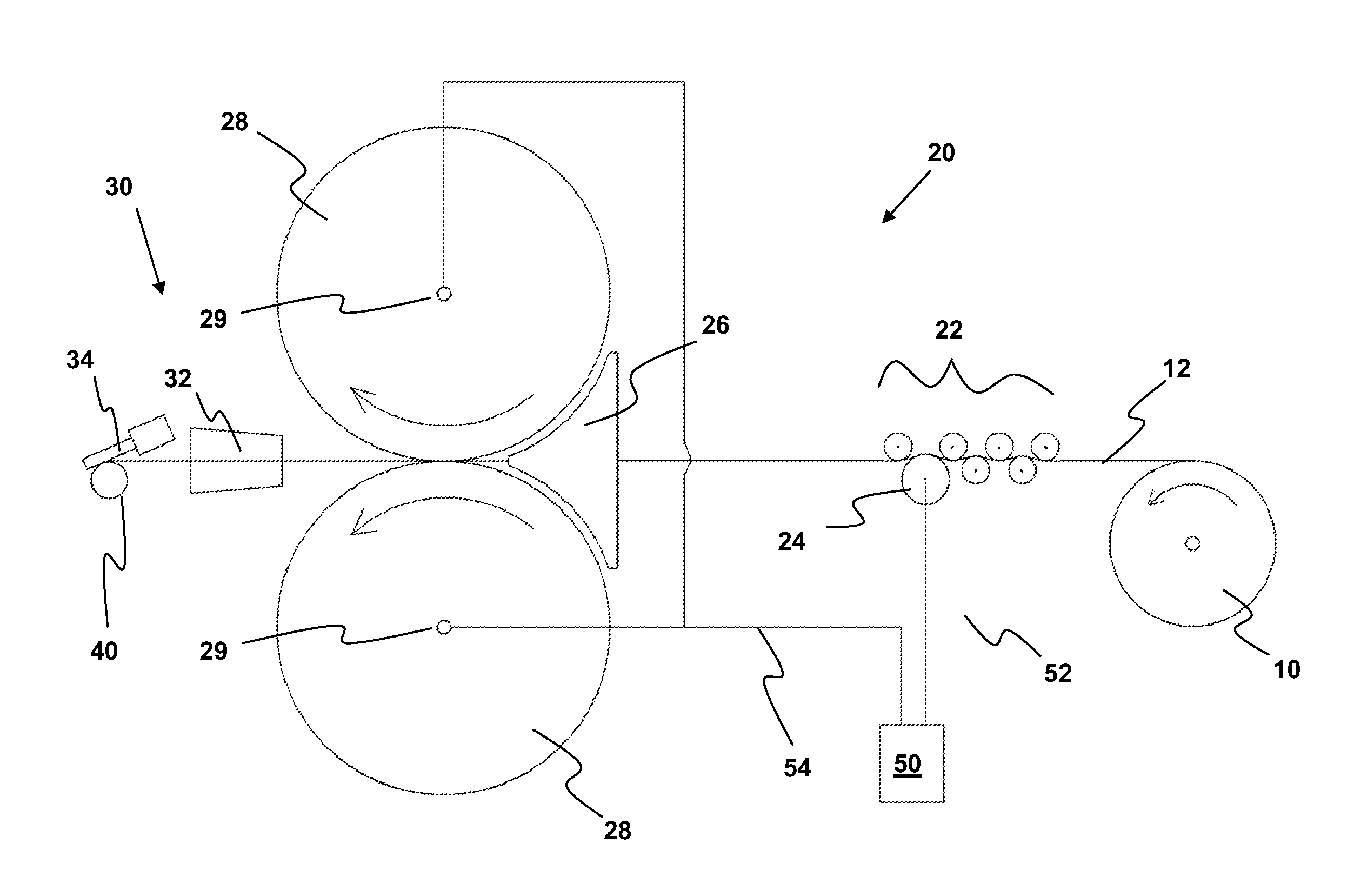
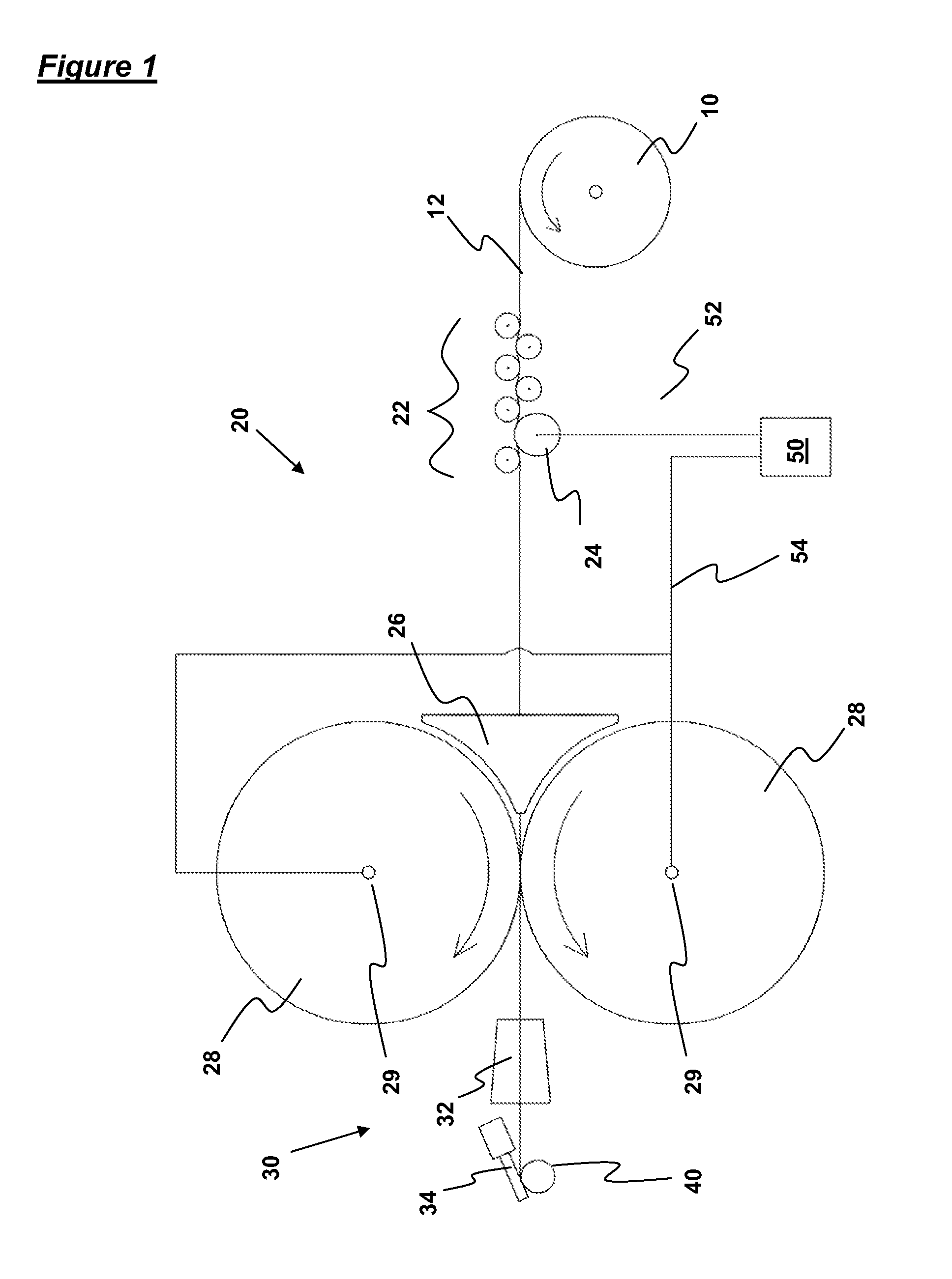
FIG. 1 shows apparatus according to the invention comprising a feed assembly 20 and a coiling assembly 30, which are together adapted to form coil springs 40. In particular, the feed assembly 20 feeds a continuous wire 12 from a wire roll 10 to the coiling assembly 30, where the wire 12 is deformed into a coil and then severed from the remainder of the wire 12, in order to form a coil spring 40.

The wire roll 10 comprises a rotatable spool, on which is wound a continuous metal wire 12. This wire is formed of steel, having a diameter in the range of 0.5 mm to 3.0 mm. From the wire roll, the wire 12 is fed through a set of straightening rollers 22, a guide block 26 and a pair of feed rollers 28.

The straightening rollers 22 are arranged in two rows, which define a non-linear path for the wire 12 therebetween. In particular, the straightening rollers 22 are arranged in a hexagonal packed arrangement, but with sufficient separation between the rollers 22 for the wire 12 to be only slightl...

second embodiment

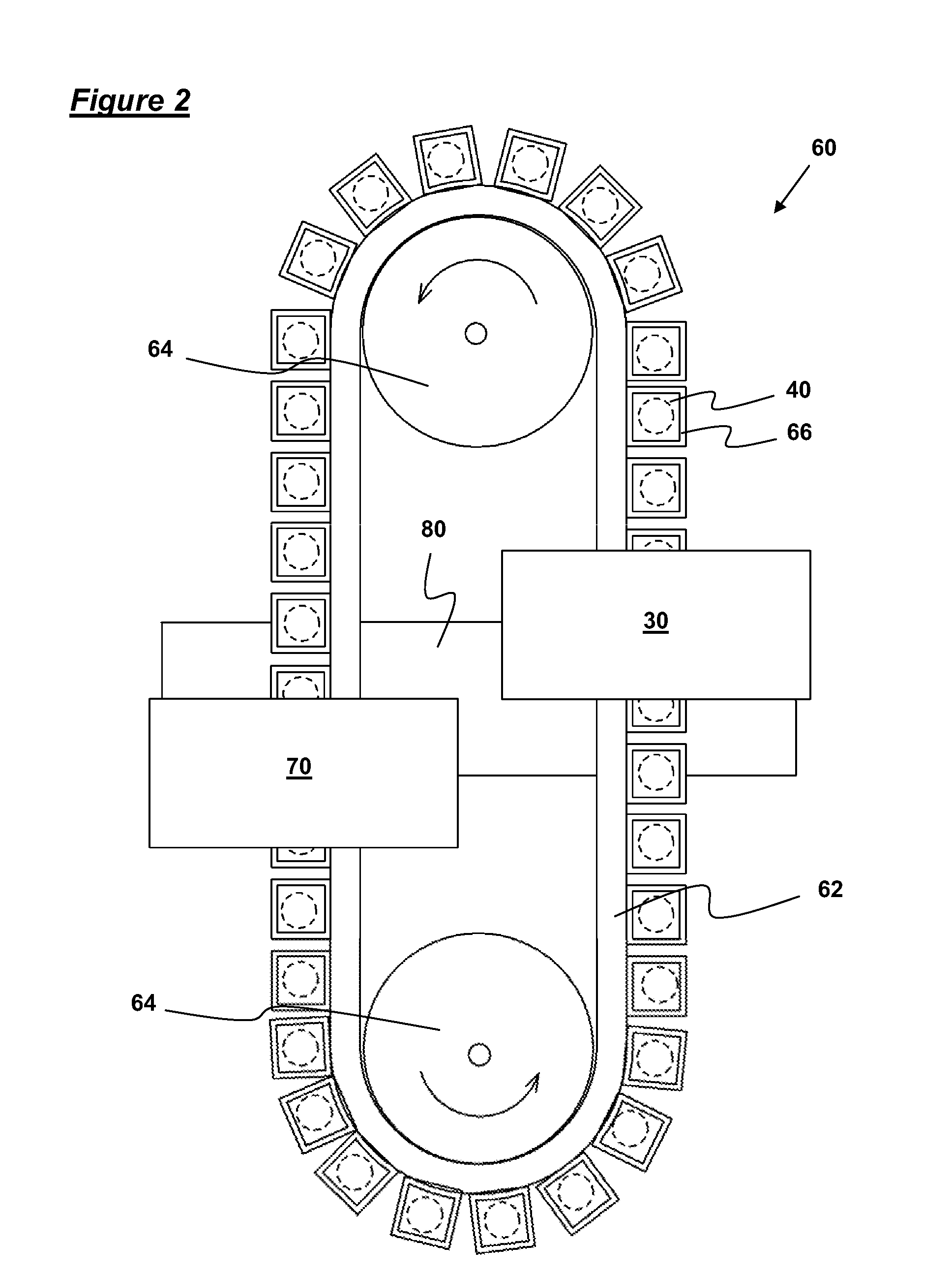
Nevertheless, since the conveyor mechanism 60 of the second embodiment enables two springs 40 to be delivered to the encapsulation assembly 80 substantially simultaneously, the encapsulation assembly 80 of this embodiment is adapted to encapsulate two coil springs within respective pockets, substantially simultaneously. In particular, the encapsulation assembly 80 is adapted to feed two coil springs 40 simultaneously into the space between two plies of a weldable fabric, the two plies then being sealed together (using two cross welds and a double-length end weld) to form two pockets, which each encapsulate a coil spring 40. The fabric is then indexed forward a distance equal to two pocket widths, the next two springs 40 encapsulated, and so on.

The continuous chain of pocketed coil springs is then fed into apparatus for forming strings and fastening those strings together with adhesive. Conventional apparatus may be used for this process. However, particularly suitable apparatus is d...


PUM

PropertyMeasurementUnit
Temperatureaaaaaaaaaa
Timeaaaaaaaaaa
Flow rateaaaaaaaaaa

Abstract

An apparatus is disclosed for the manufacture of a coil spring from a wire. The apparatus comprises first and second tools for contacting the wire prior to, and/or during, deformation of the wire into a coil spring. The apparatus includes means for applying an electrical potential difference between the first and second tools such that an electric current is caused to flow through at least part of the wire during use.

Description

CROSS REFERENCE TO RELATED APPLICATIONThis application claims priority from United Kingdom patent number UK 0823067.4 filed Dec. 18, 2008, incorporated herein by reference in its entirety.TECHNICAL FIELDThis invention relates to apparatus for the manufacture of coil springs, and in particular pocketed coil springs.BACKGROUNDPocketed coil springs, i.e. coil springs enclosed within pockets of fabric which are joined at their side seams, are widely used in the manufacture of mattresses, cushions and the like. Apparatus for the production of pocketed coil springs generally comprises a coiling assembly in which a coil spring is formed from wire, and an encapsulation assembly in which the coil spring is encapsulated within a pocket. In particular, the coil spring is generally formed in the coiling assembly, and then fed directly to the encapsulation assembly in which the coil spring is inserted between two sheets of a weldable fabric, the two sheets then being sealed together to form a po...

Claims


Application Information

Patent Timeline
IPC IPC(8): B21F37/00
CPCB21F3/02B21F33/04B21F99/00B68G9/00C21D1/40Y10T29/49613C21D9/02C21D9/54C21D9/62C21D9/06C21D8/06
Inventor WHITWORTH, IAN JAMES
Owner SPRINGFORM TECH
Why Eureka
Try Eureka