Control apparatus for internal combustion engine

a control apparatus and internal combustion engine technology, applied in combustion engines, condensed fuel collection/return, charge feed systems, etc., can solve the problem of inability to supply vaporized fuel immediately into the cylinder, and achieve the effect of improving startability

Inactive Publication Date: 2011-10-13
TOYOTA JIDOSHA KK
View PDF5 Cites 15 Cited by
  • Summary
  • Abstract
  • Description
  • Claims
  • Application Information

AI Technical Summary

Benefits of technology

[0007]The invention thus provides a control apparatus for an internal combustion engine, that is capable of immediately supplying vaporized fuel into the cylinders, and thus improve startability, even under conditions in which fuel does not easily vaporize, such as during a cold start.

Problems solved by technology

Therefore, with the technology described above, it takes time to produce vaporized fuel at startup, so vaporized fuel is unable to be immediately supplied into the cylinders.

Method used


Image

  • Control apparatus for internal combustion engine
  • Control apparatus for internal combustion engine
  • Control apparatus for internal combustion engine

Examples


first example embodiment

[0022][Structure of the First Example Embodiment]

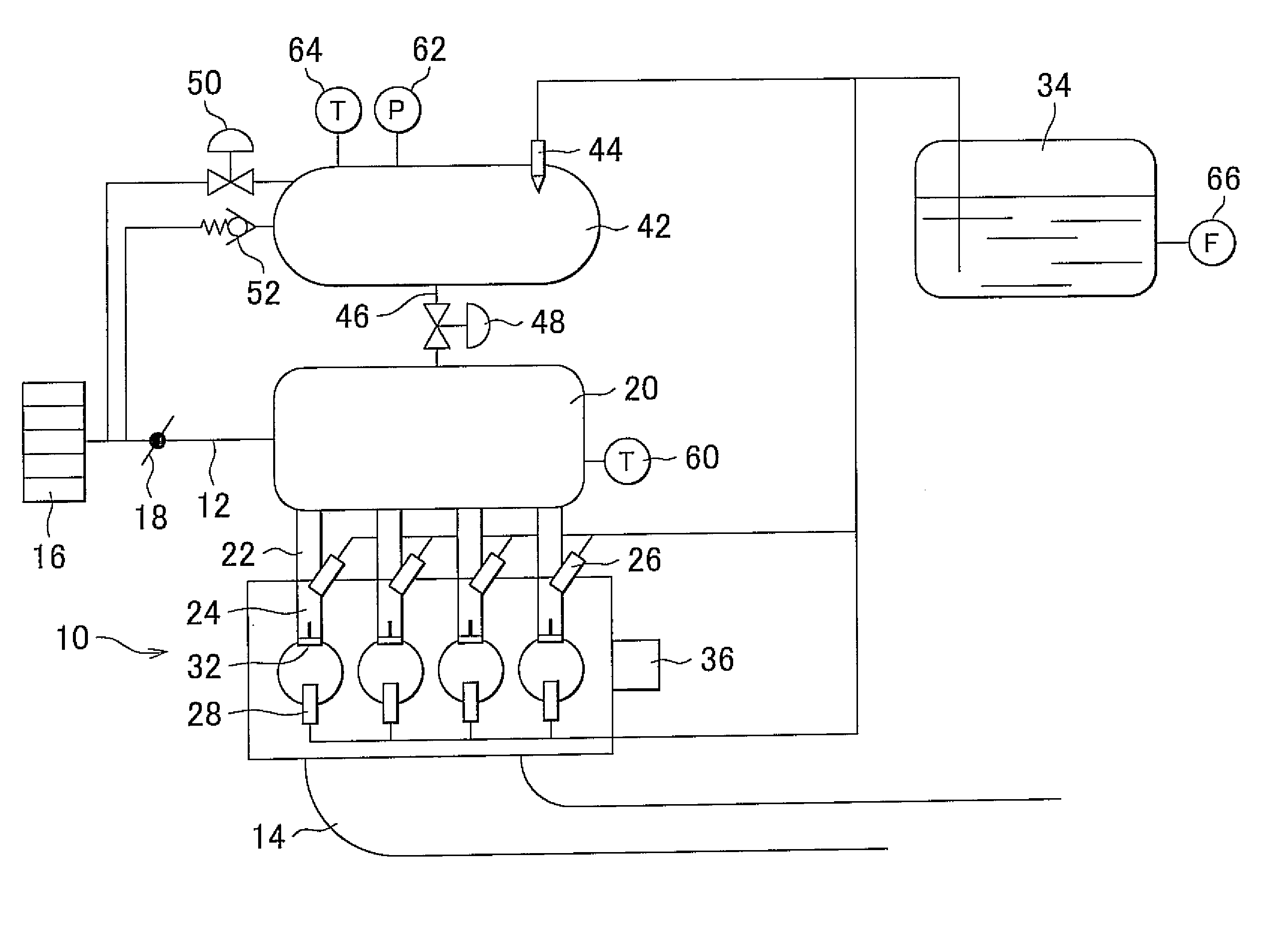
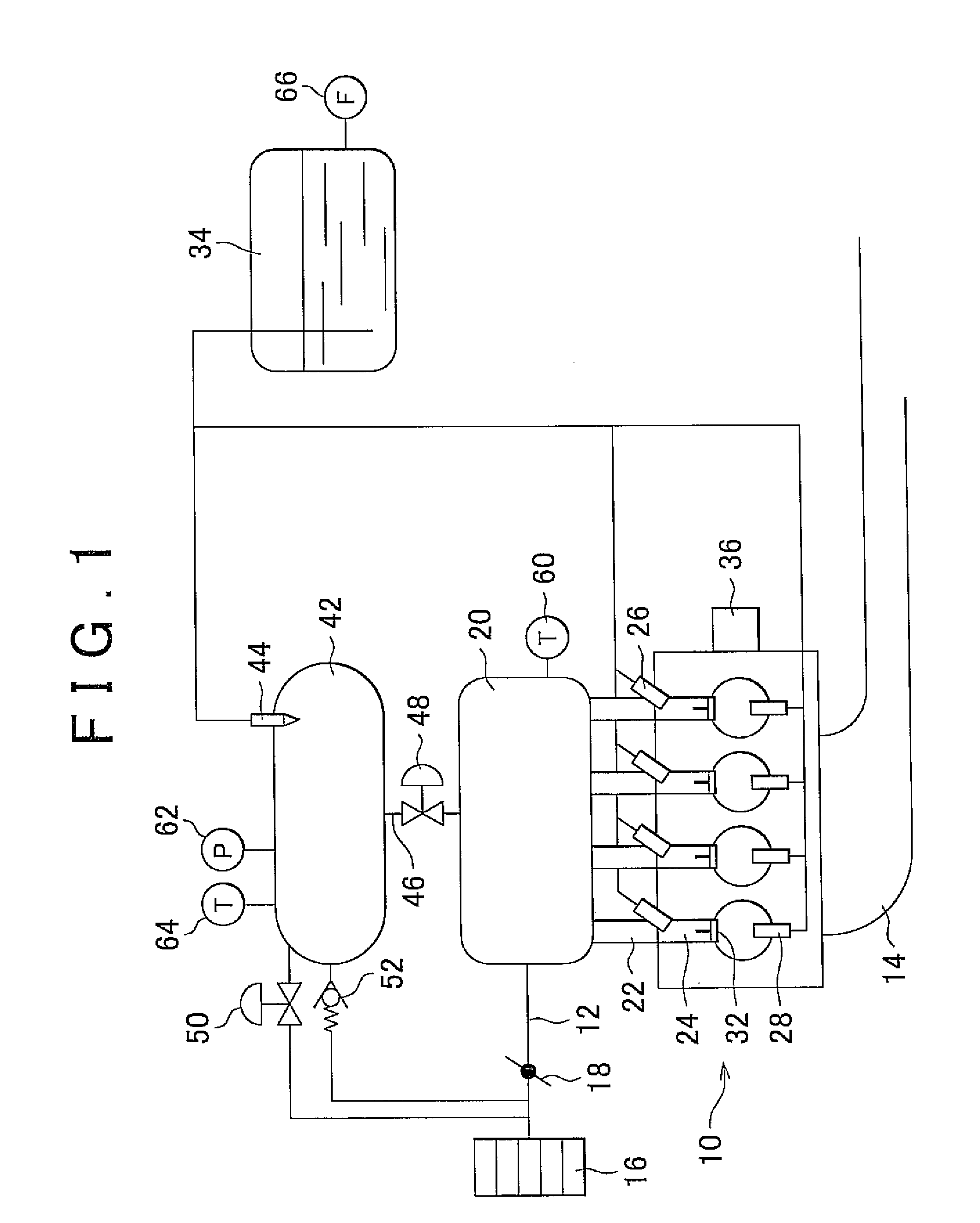
[0023]Hereinafter, a first example embodiment of the invention will be described with reference to FIGS. 1 to 6. FIG. 1 is an overall block diagram of a system configuration according to the first example embodiment of the invention. The system in this example embodiment includes an engine 10 as an internal combustion engine mounted in a FFV (Flexible Fuel Vehicle). Incidentally, a four cylinder engine is shown in FIG. 1, but the invention is not limited to a four cylinder internal combustion engine. The engine 10 includes an intake passage 12 through which air is drawn into combustion chambers of cylinders, and an exhaust passage 14 through which exhaust gas is discharged from the combustion chambers.

[0024]An air cleaner 16, a throttle valve 18, and a surge tank 20 are provided in order from the upstream side in the intake passage 12. The throttle valve 18 is formed by an electronically controlled butterfly valve. The throttle valve ...

second example embodiment

[0064]Next, a second example embodiment of the invention will be described with reference to FIGS. 7 and 9. This second example embodiment employs a structure and control (FIGS. 1, 2, and 5) that are almost the same as those of the first example embodiment described above, except that the operation angle and phase of the intake valve are controlled based on the throttle opening amount. Incidentally, constituent elements in this second example embodiment that are the same as those in the first example embodiment will be denoted by the same reference characters, and descriptions of those constituent elements will be omitted.

[0065][Characteristics of the Second Example Embodiment]

[0066]In this example embodiment, the supply flow rate of the vaporized fuel is controlled based on the throttle opening amount, similar to the first example embodiment, but the amount of air that flows into the cylinders is controlled by changing the operation angle and the phase of the intake valve 32 based ...


PUM


Abstract

A control apparatus for an internal combustion engine includes a fuel tank; a vaporized fuel tank that is connected to an intake passage; an in-tank fuel supplying portion that supplies fuel in the fuel tank to the vaporized fuel tank; a vaporized fuel supply valve that opens and closes a connecting portion between the vaporized fuel tank and the intake passage; an air introduction valve provided in the vaporized fuel tank; a throttle valve; a vaporized fuel producing portion that produces vaporized fuel in the vaporized fuel tank; a vaporized fuel supplying portion that supplies vaporized fuel stored in the vaporized fuel tank; and a supply amount controlling portion that controls a supply amount of vaporized fuel according to an opening amount of the throttle valve by driving the throttle valve when supplying vaporized fuel.

Description

CROSS-REFERENCE TO RELATED APPLICATIONS[0001]This application claims priority to Japanese Patent Application No. 2010-089574 filed on Apr. 8, 2010, which is incorporated herein by reference in its entirety including the specification, drawings and abstract.BACKGROUND OF THE INVENTION[0002]1. Field of the Invention[0003]The invention relates to a control apparatus for an internal combustion engine that uses low volatile fuel such as alcohol fuel, for example.[0004]2. Description of the Related Art Japanese Patent Application Publication No. 2007-224878 (JP-A-2007-224878) describes a control apparatus for an internal combustion engine that uses alcohol fuel. Alcohol fuel does not easily vaporize particularly at low temperatures, so a vaporizing chamber to vaporize the fuel at startup is provided in an internal combustion engine. This vaporizing chamber has a closed structure in which it is cut off from the outside, and is connected to an intake passage via a reduced passage. Also, a s...

Claims


Application Information

Patent Timeline
Patent Type & Authority Applications(United States)
IPC IPC(8): F02M33/02
CPCY02T10/126F02M31/18Y02T10/12
Inventor YOSHIZAKI, SATOSHIIRISAWA, YASUYUKIMITANI, SHINICHITSUNOOKA, TAKASHISATOU, AKIRAURANO, SHIGEYUKI
Owner TOYOTA JIDOSHA KK
Why Eureka
Try Eureka