Movable cooking appliance

a technology for cooking appliances and cooking trays, which is applied in the direction of heating types, domestic stoves or ranges, and coupling device connections, etc. it can solve the problems of potential breakdown of the insulated gate, risk of electric arcing at the power terminal, and the design of the connectors that do not implement any further safety features, so as to achieve safer and more reliable insertion and extraction.

Active Publication Date: 2011-10-13
WHIRLPOOL CORP
View PDF4 Cites 19 Cited by
  • Summary
  • Abstract
  • Description
  • Claims
  • Application Information

AI Technical Summary

Benefits of technology

[0007]The present invention is focused on the design of a connector that is to be used to connect an induction tray into a socket of an oven cavity or other type of support used for the tray. In a preferred embodiment of the invention, the connector has five male terminals, including two for the power connection (i.e., supplying an induction heating coil), two for the temperature sensor connection (that allows a readin

Problems solved by technology

The design of these connectors doesn't implement any further safety feature that guarantees power supply cut-off when the user is extracting the removable tray with an induction heater while the tray is working.
This abnormal procedure may happen

Method used


Image

  • Movable cooking appliance
  • Movable cooking appliance
  • Movable cooking appliance

Examples


first embodiment

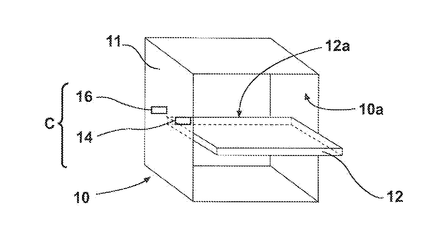
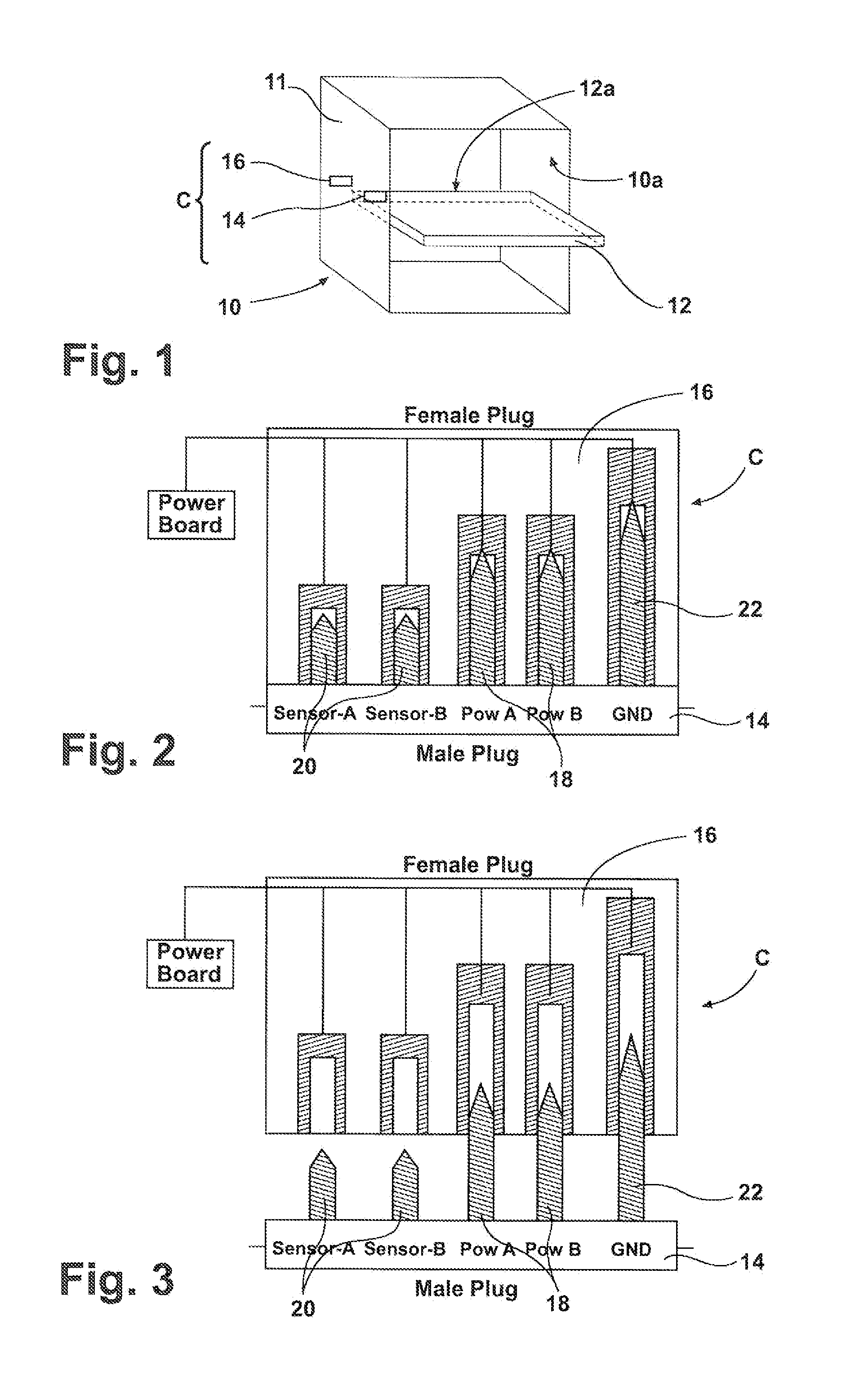
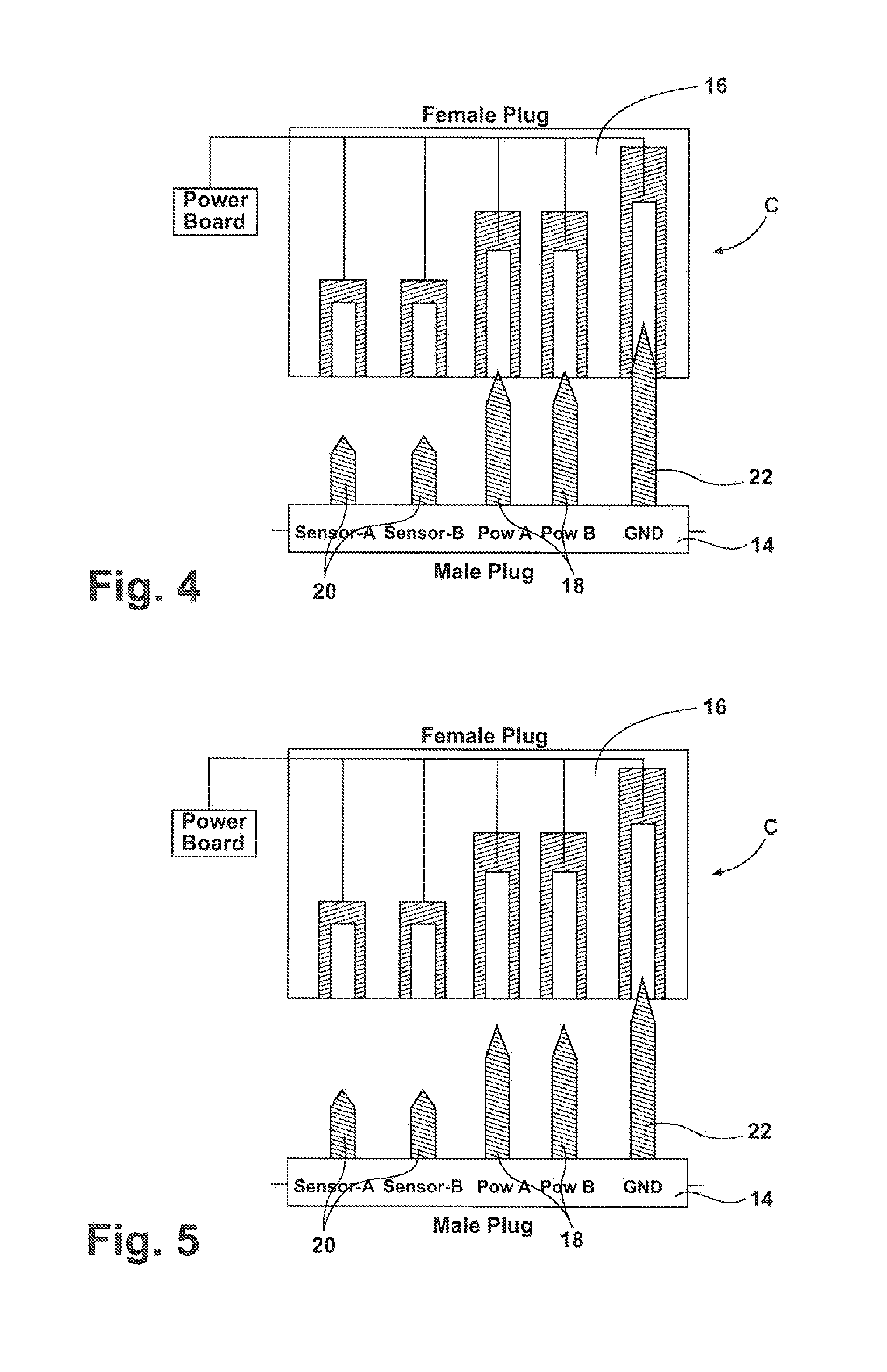
[0025]According to the present invention depicted in FIG. 1, the design of connector C presents assemblies of five male terminals and associated female terminals which make up a total of five connections. Two sets of the terminals 18 provide power connections, two sets of the terminals 20 are for the temperature sensor connection and one set including terminal 22 is for the ground connection. As shown in the embodiment of FIG. 2, the ground terminal 22 has the greatest length, the sensor terminals 20 (equal to each other in length) are the shortest ones and the power terminals 18 (equal to each other in length) have an intermediate length between the lengths of the ground terminal 22 and of the sensor terminals 20. This design enables the ground terminal 22 to connect first during insertion of plug 14, and to disconnect last during extraction of the plug 14, guaranteeing safety electrical discharge through ground terminal 22 in case there might be a discharge between induction coil ...

second embodiment

[0026]According to the invention depicted in FIG. 6, inside the female plug 16 there is a switch 24 that is electrically closed by the ground plug 22 when inserting the male plug 14. This circuit is connected to power board P of the oven. The switch 24 can be of any kind. For instance, it can be a mechanical switch (that is in physical contact with the terminals) or it can be a proximity switch (that doesn't need a physical contact), such as a reed switch 40 shown in FIGS. 13 and 14. This switch mechanism 24 can be short-circuited and open-circuited, distinguishing the cases between complete male plug insertion and not complete insertion, respectively. As can be seen in FIG. 6, the extraction of the male plug 14 from the female socket 16 including mechanical switch 24 causes the opening of the circuit, sending therefore a signal to the power board P to interrupt the power supply to the tray 12 before the power terminals 18 are disconnected.

[0027]It is clear that the position of the ...


PUM


Abstract

A movable cooking appliance comprises a structure which is adapted to be placed on a kitchen worktop appliance or inside a cooking oven appliance and includes a heating element and releasable connector assembly for making electrical connection with power supply connectors. The heating element is an induction heating element and an electronic driving unit is mounted on the appliance. The releasable connector assembly comprising a plug connector having a plurality of terminals designed in order to provide a disconnection signal to the electronic unit before the power supply connectors are fully extracted.

Description

BACKGROUND OF THE INVENTION[0001]1. Field of the Invention[0002]The present invention relates to movable cooking appliances or cooking trays including structure which is adapted to be placed on a worktop of kitchen furniture or inside a cooking oven (collectively referred to as a cooking unit), and includes a heating element and releasable connector means for making electrical connection with power supply connector means. With the term “movable” we mean any kind of cooking and heating appliance which can be plugged or unplugged to a fixed support, whatever such support is.[0003]2. Description of the Related Art[0004]The above kind of cooking appliances or cooking accessories are well known in the art. An example is shown in U.S. Pat. No. 5,272,317. With the known appliances the heating element is an electrical resistance heater connected, for instance, to a shelf or tray adapted to be introduced into an oven cavity. The use of electrical resistance heaters has been replaced by more ...

Claims


Application Information

Patent Timeline
IPC IPC(8): H05B6/12
CPCF24C15/16H01R13/7037H01R13/7032F24C15/166
Inventor GUTIERREZ, DIEGO NEFTALISANTACATTERINA, GIANPIEROFARACHI, FRANCESCO
Owner WHIRLPOOL CORP
Why Eureka
Try Eureka