Generator with ferromagnetic teeth

a technology of ferromagnetic teeth and generators, which is applied in the direction of electric generator control, magnetic circuit rotating parts, magnetic circuit shape/form/construction, etc., can solve the problems of high losses due to saturation of iron teeth, increased densities, and significant increase in the magnetomotive forces generated by windings and other problems, to achieve the effect of low cost, increased overall performance, and reduced cos

Active Publication Date: 2011-10-13
AMERICAN SUPERCONDUCTOR
View PDF6 Cites 10 Cited by
  • Summary
  • Abstract
  • Description
  • Claims
  • Application Information

AI Technical Summary

Benefits of technology

[0010]Superconducting electric machines are ideally suited for use in wind turbine applications as a wind-driven direct-drive generator. Due to the low frequency (10 Hz or less) output of a wind turbine, a low cost superconducting generator can be provided that includes stator winding support formed of a ferromagnetic material, without incurring the large power losses associated with high operating frequency generators. Use of a stator winding support formed of a ferromagnetic material results in a relatively low cost generator.
[0011]As will be described in greater detail below, the inventive stator assembly has features which contribute toward increasing the overall performance, as well as reducing the overall manufacturing cost of a HTS generator. In particular, the low frequency superconducting generator permits a stator support design in which the ratio of overall slot area to overall support area is greater than 60 percent. Due to the relative large slot size, the cross sectional area of the conductor within the slot is much greater than in a conventional machine, providing increased power generation.
[0012]In some embodiments, by selecting a particular stator winding configuration, a single winding is disposed in a corresponding slot. As a result, the cross sectional area of the conductor within the slot is further increased relative to other stator winding configurations, in which a single slot is occupied by leg portions of two or more stator windings, and in which insulation disposed between individual leg portions reduces overall conductor cross sectional area.
[0013]A generator includes a stator core formed of ferromagnetic laminations and including plurality of teeth provided to support stator coil windings. Use of ferromagnetic material to form the stator support reduces manufacturing costs relative to use of fiber composite materials. Although the ferromagnetic teeth of the stator support become highly saturated, the generator is operated at relatively low frequency, whereby the power losses associated with higher frequency machines due to teeth saturation, as well as due to copper and heat generation, are minimized.
[0014]The superconducting synchronous generator can be shown to produce stator tooth flux densities that are greater than 2.8 Tesla at generator operating frequencies of 10 Hz or less. In addition, employing an air gap greater than 15 to 20 mm between the stator and rotor assemblies in these machines further reduces losses.

Problems solved by technology

The use of superconducting windings in these machines has resulted in a significant increase in the magnetomotive forces generated by the windings and increased flux densities in the machines.
The flux densities were increased to such an extent that there were high losses due to saturation of the iron teeth, as well as due to eddy current losses.
As a result, superconducting machines have been developed to operate without iron teeth between the stator coils since the flux density would result in high dissipation in these members.
However, such fiber composite teeth are very expensive to manufacture.

Method used


Image

  • Generator with ferromagnetic teeth
  • Generator with ferromagnetic teeth
  • Generator with ferromagnetic teeth

Examples


Embodiment Construction

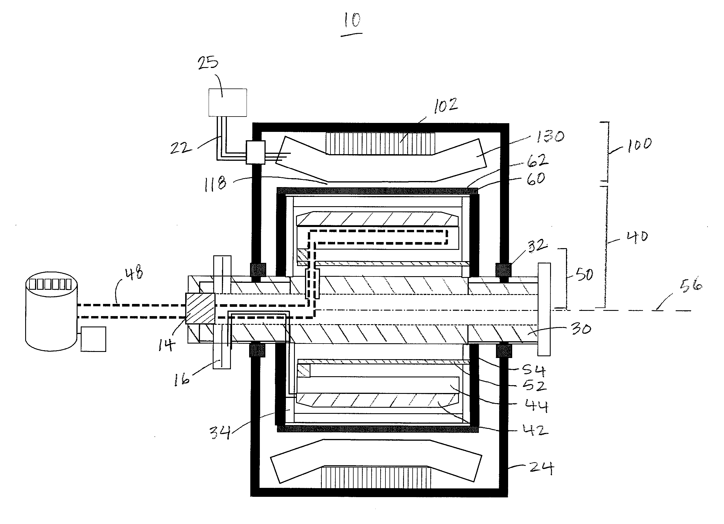
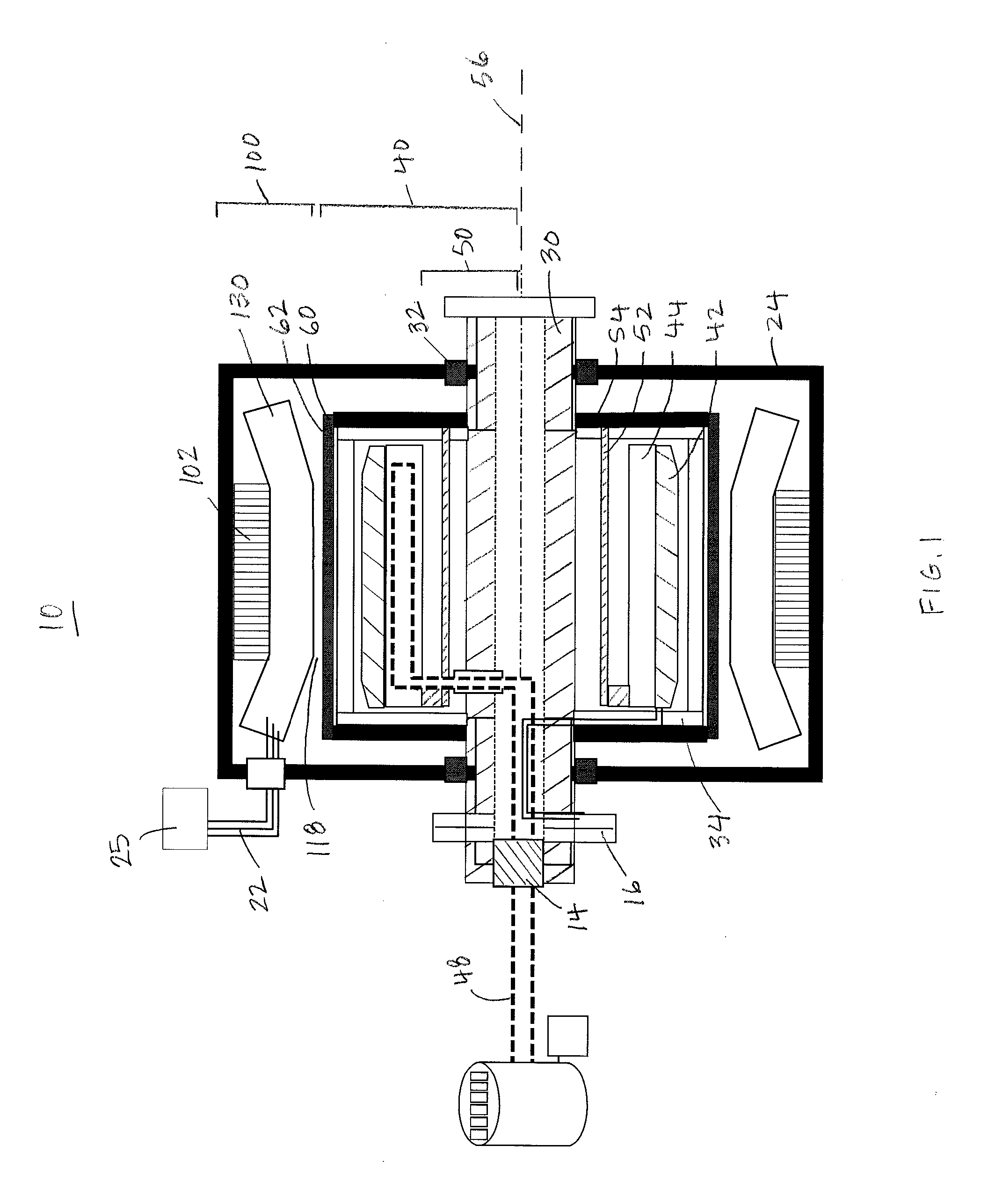
[0031]Referring now to FIG. 1, generator 10 is a rotating superconducting machine that includes a rotor assembly 40 mounted within a stator assembly 100. As will be described in greater detail below, the generator 10 is configured for use in low frequency applications of 10 Hz or less. For example, when generator 10 is used as a generator in a wind turbine, the rotor and stator assemblies 40, 100 are configured to operate at about 2 Hz.

[0032]The rotor assembly 40 includes rotor windings 42 formed of a high-temperature superconductor (HTS), a torque transfer system 50, and an electromagnetic shield 60. The rotor windings 42 are supported by a rotor winding support structure 44 within a cryostat 34. Although other configurations are possible, the rotor windings 42 of this embodiment include several HTS sub-coils formed in a racetrack configuration. U.S. Pat. No. 6,509,819, the entire contents of which are incorporated herein by reference, discusses exemplary rotor coil configurations ...


PUM


Abstract

A stator assembly for use in a superconducting generator operated at frequencies up to 10 Hz is disclosed. The stator assembly includes a ferromagnetic stator winding support having a plurality of teeth defining slots, the slots configured to receive and support stator windings. The stator winding support is formed so that the ratio of the sum of the widths of the slots to the sum of the widths of the teeth and slots is in the range of 0.65 to 0.90.

Description

CROSS-REFERENCE TO RELATED APPLICATIONS[0001]This application is a continuation of U.S. application Ser. No. 12 / 568,742, filed on Sep. 29, 2009, the contents of which are hereby incorporated by reference.GOVERNMENT RIGHTS STATEMENT[0002]The U.S. Government has a paid-up license in this invention and the right in limited circumstances to require the patent owner to license others on reasonable terms as provided for by the terms of Contract No. 70 NANB7H7055 awarded by the National Institute of Standards and Technology / Advanced Technology Program.BACKGROUND OF THE INVENTION[0003]Power generation continues to be an important application of rotating electrical machines. Wind energy is one of the fastest growing sources of electricity in the United States and around the world, and wind turbines employing rotating electrical machines are used to convert wind energy to usable power. The generator component of a wind turbine includes the electrical generator, control electronics, and an opt...

Claims


Application Information

Patent Timeline
Patent Type & Authority Applications(United States)
IPC IPC(8): F03D9/00H02K1/16
CPCH02K1/165H02K55/04H02K7/1838Y02E10/725Y02E40/625H02K2213/03Y02E10/72Y02E40/60H02K55/00H02K1/16
Inventor SNITCHLER, GREGORY L.MACDONALD, TIMOTHY
Owner AMERICAN SUPERCONDUCTOR
Why Eureka
Try Eureka