Determining initial rotor position of an alternating current motor

a technology of alternating current motor and initial rotor position, which is applied in the direction of motor/generator/converter stopper, electronic commutator, dynamo-electric converter control, etc., can solve the problem of increasing the size, weight and complexity of the ac motor system, insufficient back electromotive force (emf) generated in the motor to enable an accurate estima

Active Publication Date: 2011-10-13
NXP USA INC
View PDF1 Cites 42 Cited by
  • Summary
  • Abstract
  • Description
  • Claims
  • Application Information

AI Technical Summary

Benefits of technology

[0010]These and other aspects of the invention will be apparent from and elucidated with reference to the embodiments described hereinafter.

Problems solved by technology

Physical position sensors, such as position and velocity transducers, can be used although such position sensors and their associated cabling and connectors increase the size, weight and complexity of the AC motor system and have also been a source of failure for AC motor systems.
However, at rotor standstill or low speed there is insufficient back electromotive force (EMF) generated in the motor to enable an accurate estimate of rotor position.
These known techniques where the command voltage signals are applied to generate the stator drive current simultaneously with the injected HF carrier signal, torque is applied to the rotor before its initial standstill position is known and the rotor moves, delaying and disturbing determination of its estimated position.

Method used


Image

  • Determining initial rotor position of an alternating current motor
  • Determining initial rotor position of an alternating current motor
  • Determining initial rotor position of an alternating current motor

Examples


Embodiment Construction

[0016]The present disclosure will be described with reference to a 3-phase Permanent Magnet Synchronous motor. It will be appreciated that the disclosure is not limited to use with a 3-phase Permanent Magnet Synchronous motor and may apply to any AC motor with saliency, for example 2-phase AC motors, wound-rotor AC motors, a permanent magnet motor with the permanent magnet buried in the motor or surface mounted, a Synchronous Reluctance Motor (SynRM), a Switched Reluctance Motor (SRM), or an AC Induction Motor (ACIM).

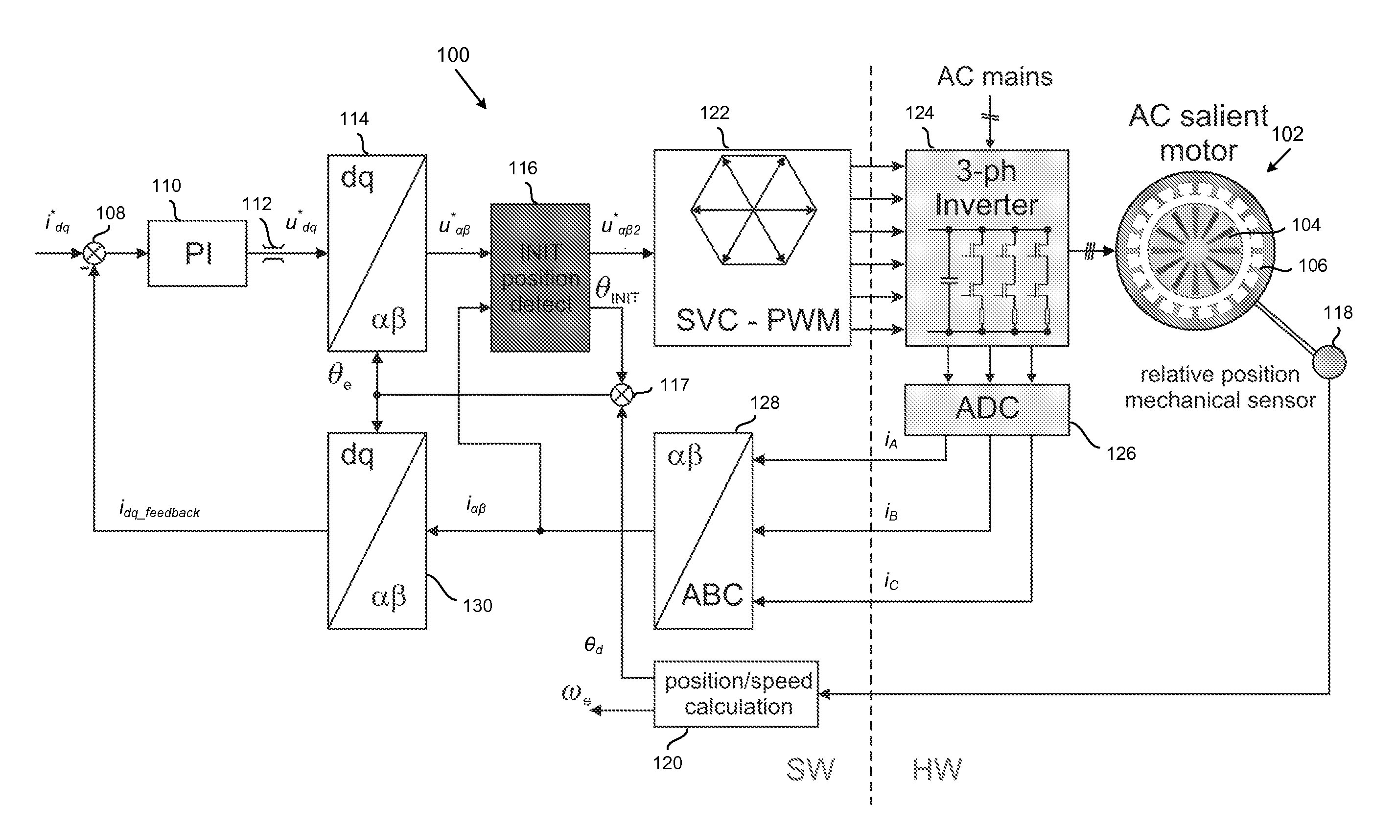
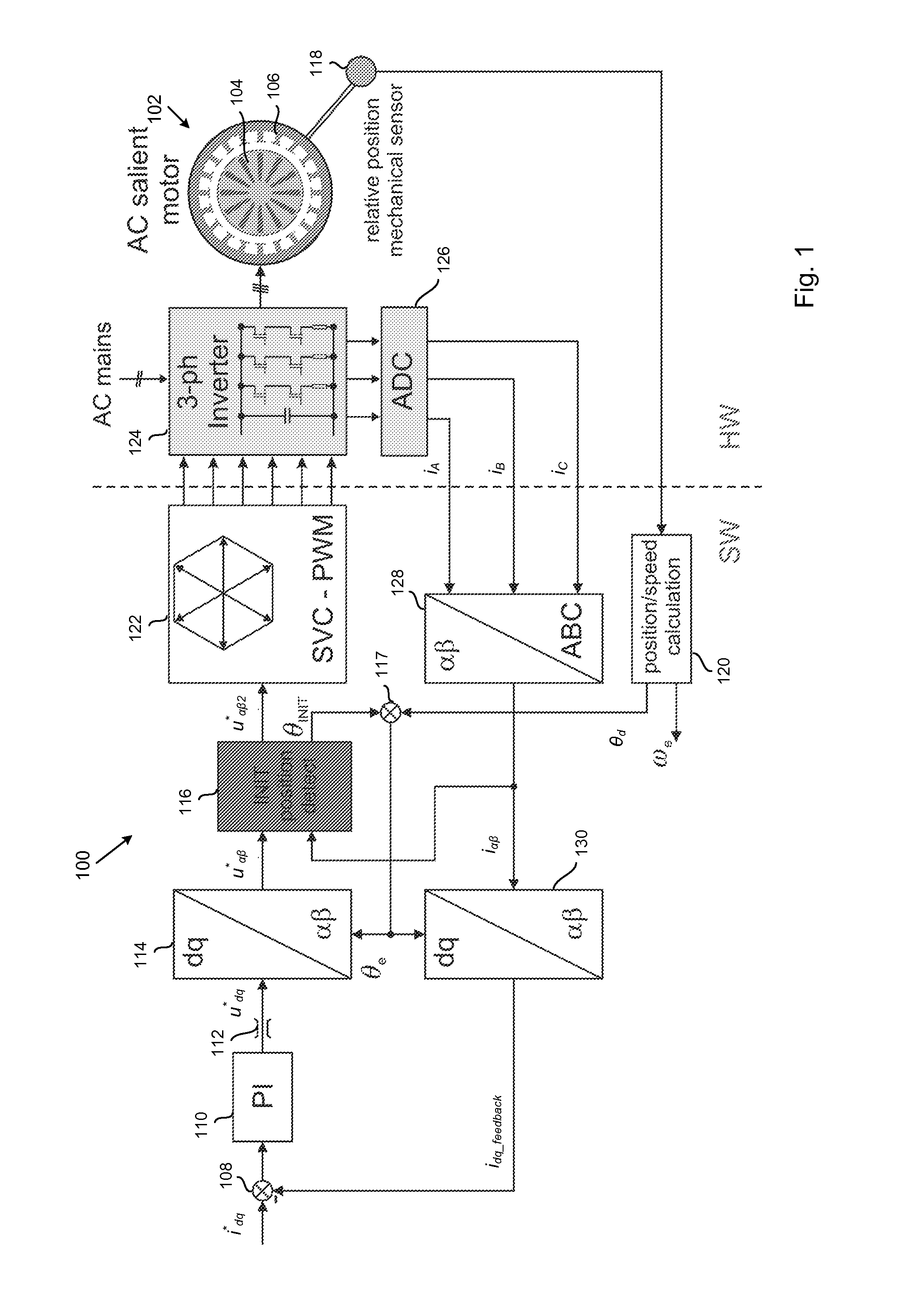
[0017]FIG. 1 shows a controller 100 in accordance with an embodiment of the present invention for an alternating current (‘AC’) salient electric motor 102 which has a rotor 104 and a stator 106. The controller of FIG. 1 calculates values in direct (‘D-axis’) and quadrature (‘Q-axis’) coordinates which rotate relative to the stator before transforming the values to α, β angular coordinates that are static relative to the stator and which in turn are then transformed to s...


PUM


Abstract

Determination of an estimated initial angular position of the rotor of an AC motor includes application of voltages corresponding to a high frequency reference signal vector to the stator windings of the motor and production of an estimated initial angular position of the rotor as a function of the resulting q-axis stator current component iq_HF, adjustment of transformation of signal vectors from stationary to rotating coordinates and vice versa using the estimated angular position, and production of an adjusted estimated angular position of the rotor as a function of the q-axis stator current component as adjusted. Determination of an initial estimated angular position of the rotor and production of an adjusted initial estimated angular position of the rotor is performed with the rotor at standstill and before initially applying voltage corresponding to the drive signal vector to the stator windings, and production of an initial value of a drive signal vector command in stationary coordinates uses the adjusted estimated angular position. Determination of an estimated angular position of the rotor after application of stator current may use a different method, such as a physical relative position sensor.

Description

FIELD OF THE INVENTION[0001]This invention relates to determining the initial rotor position of an alternating current motor.BACKGROUND OF THE INVENTION[0002]Alternating current (‘AC’) motor systems typically comprise a motor comprising a rotor and a stator and a motor controller for controlling the voltage and current supplied to drive the motor. In order to ensure good control of the motor, for example in order to meet specified motor performance requirements, the motor controller needs to know the position of the motor rotor.[0003]Various techniques are known for estimating the rotor position. Physical position sensors, such as position and velocity transducers, can be used although such position sensors and their associated cabling and connectors increase the size, weight and complexity of the AC motor system and have also been a source of failure for AC motor systems. In order to eliminate such position sensors, particularly for small low cost motor controllers, much research h...

Claims


Application Information

Patent Timeline
Patent Type & Authority Applications(United States)
IPC IPC(8): H02P6/18
CPCH02P6/183H02P6/185H02P2203/11H02P21/146H02P21/0053H02P21/32H02P21/18
Inventor BALAZOVIC, PETERFILKA, ROMAN
Owner NXP USA INC
Why Eureka
Try Eureka