
Control Module for a Field Device

Inactive Publication Date: 2011-10-13
VEGA GRIESHABER GMBH & CO
View PDF13 Cites 9 Cited by
  • Summary
  • Abstract
  • Description
  • Claims
  • Application Information

AI Technical Summary

Benefits of technology

[0011]This may reduce the costs and effort required for the maintenance of field devices.
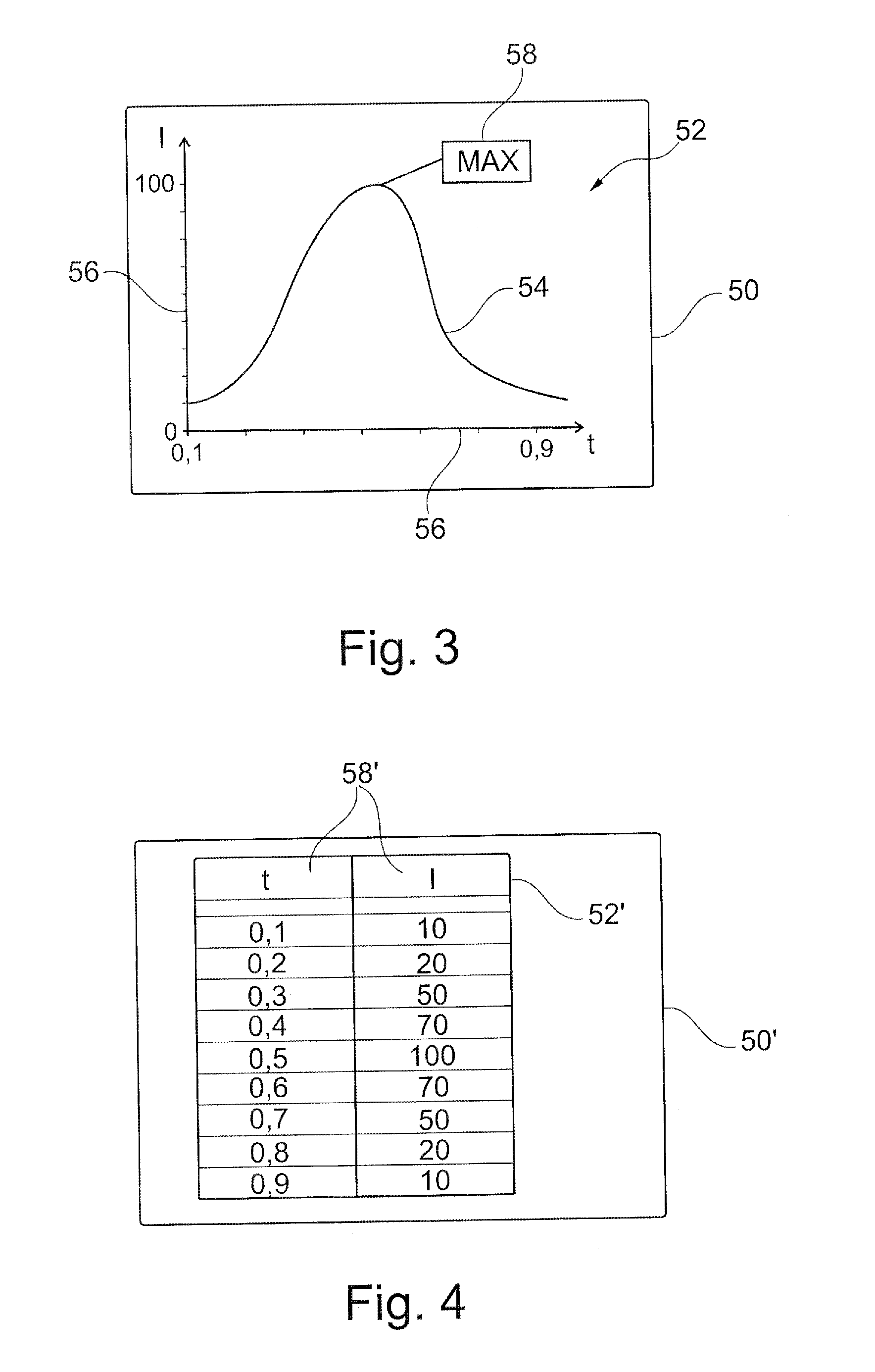
[0015]Furthermore, it is also possible for (raw) image data that already exists in the image processing module to be enriched with the process data. For example, in the image processing module the image of a blank diagram is already present, which is joined by the image processing module with a graphic or a curve, which are parameterised by the process data. In other words, the image processing module is designed to encode process data of the field device to image data or to convert the aforesaid to image data. It is then possible for the process data to no longer be present in the image data in a form that can be interpreted particularly well by a machine, but instead to be present in a form that can easily be displayed by a display device and that is better accessible to human interpretation.
[0021]According to one embodiment of the invention, the image processing module is designed to generate a graphic from process data, which graphic represents a table. In other words, the image data comprises a table. In other words, the image data need not necessarily comprise a graphic, instead it can also comprise a table that is encoded as a graphic. For example, the image data does not comprise process data as numerical values, but instead as pixels that represent these numerical values. It is thus possible for a display device that is able to process image data and to display said image data to represent the aforesaid particularly easily without additional information on a display device.
[0025]It is possible for the control device to generate image data in different sizes, i.e. resolutions, depending on the receiving device and / or the message to be sent. Thus, image data that is, for example, sent to a computer by e-mail can comprise a typical size of 1024×768 pixels, which corresponds to a commonly used resolution. However, the control device can also generate image data of a lower resolution, for example for sending via MMS, which image data, for example, comprises a size of only 300×200 pixels. The following might be reasons for generating image data in various sizes: on the one hand, the size of the image data may already be adapted to the size of a display of the receiving device; on the other hand, smaller image data can be sent more quickly and / or economically.

Problems solved by technology

In particular, in such measuring devices remote diagnosis or remote maintenance can often prove to be difficult or even impossible.
If there is a change in the design or in the configuration of the field device or in the significance of the process data provided by a field device, or if reading-out the numerical values is to take place with a device in relation to which no specially adapted read-out software exists as yet, this can result in very considerable maintenance expenditure in relation to the read-out software.

Method used


Image

  • Control Module for a Field Device
  • Control Module for a Field Device
  • Control Module for a Field Device

Examples


Embodiment Construction

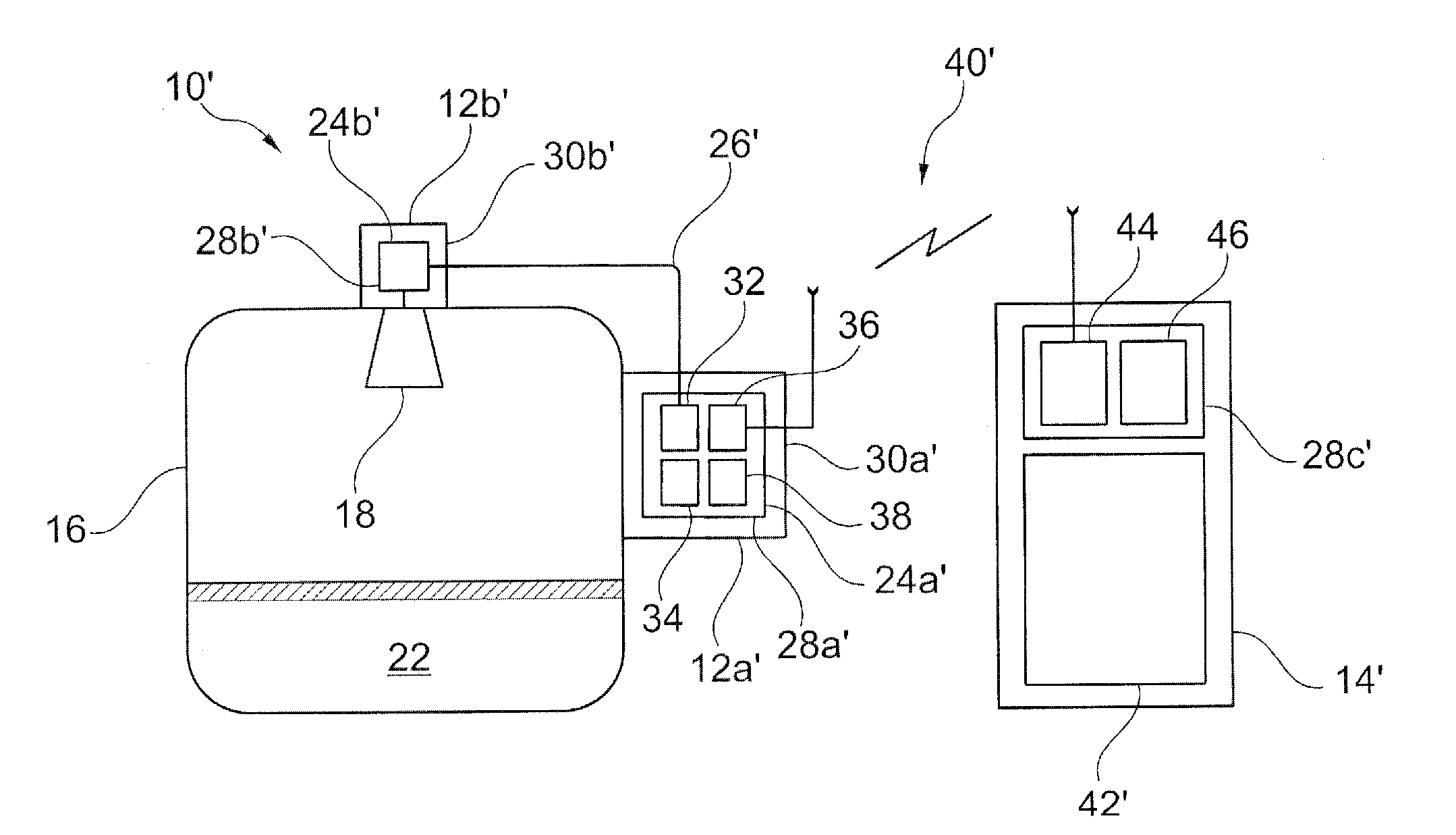
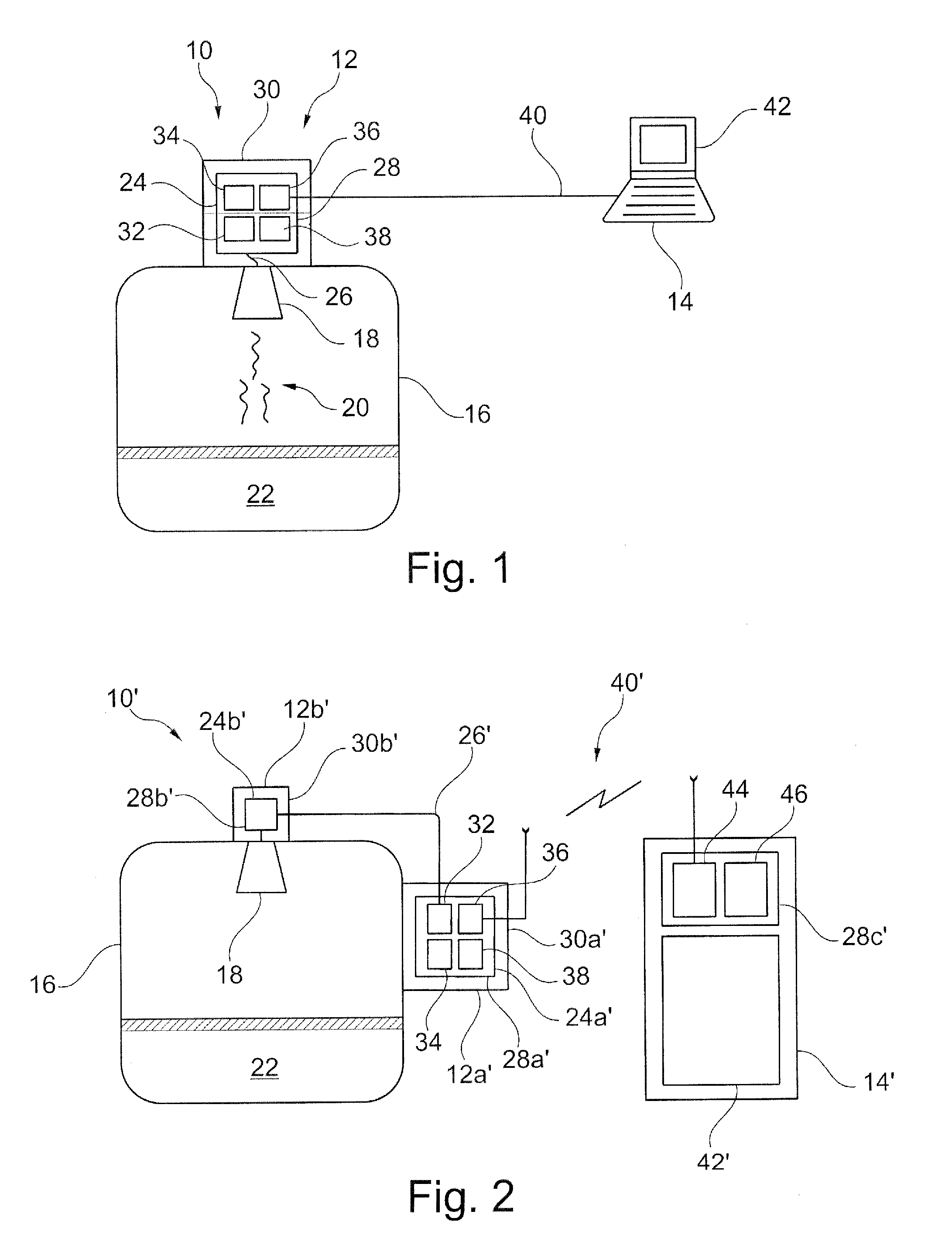
[0071]FIG. 1 diagrammatically shows an exemplary embodiment of a process monitoring system 10 with a field device 12 and a receiving device 14 in the form of a computer 14. The process monitoring system 10 is used for monitoring a technical installation with a tank 16. The field device 12 is used for monitoring the filling level of a liquid 22 in the tank 16. To this effect the field device 12 comprises a filling level radar or a measuring device 18 that emits radar rays 20 that are reflected by the surface of the liquid 22 and again reach the filling level radar 18 as a radar echo 20, whereupon they are evaluated by the field device 12.

[0072]To this effect the filling level radar 18 is connected to a control module 24 of the field device 12 by way of a communication line 26. The control module 24, which can, for example, be a printed circuit board 24 in a housing 30 of the field device 12, comprises a processor 28 on which a multitude of modules 32, 34, 36, 38 can be executed. Howe...


PUM


Abstract

A control module of a field device includes an image processing module that is able to generate an image from process data of the field device, which process data are present in numerical form, which image can be displayed by a corresponding image display unit, for example the display of a PDA, in such a manner that a person can directly interpret the process data.

Description

REFERENCE TO RELATED APPLICATIONS[0001]This application claims the benefit of the filing date of EP Patent Application Serial No. EP 09 174 497.9 filed 29 Oct. 2009, the disclosure of which is hereby incorporated herein by reference and of U.S. Provisional Patent Application Ser. No. 61 / 256,032 filed 29 Oct. 2009 the disclosure of which is hereby incorporated by reference.TECHNICAL FIELD[0002]This invention relates to the field of process control and process monitoring. In particular, the invention relates to a control module for a field device, to the field device, to a process monitoring system, to a method for controlling a field device, to a program element and to a computer-readable medium.BACKGROUND INFORMATION[0003]Process monitoring systems and process control systems, which are used for monitoring and / or controlling technical installations, for example in such various fields as foodstuffs technology, the preparation of crude oil or the manufacture of plastics, as a rule com...

Claims


Application Information

Patent Timeline
IPC IPC(8): G05B23/02G06T3/00
CPCG05B19/4185G05B19/0423G01F23/284G01S7/003Y02P90/02G01F23/80G01F25/24
Inventor ISENMANN, ANDREASALLGAIER, VOLKER
Owner VEGA GRIESHABER GMBH & CO
Learn More