Thermally compensating lens for high power lasers

a laser and thermal compensation technology, applied in the field of lasers, can solve the problems of difficult to achieve the effect of improving the optical performance of the lens system, improving the conventional technology, and improving the index of refraction

Active Publication Date: 2011-10-13
HAAS LASER TECH
View PDF3 Cites 25 Cited by
  • Summary
  • Abstract
  • Description
  • Claims
  • Application Information

AI Technical Summary

Benefits of technology

[0017]The inventive structure includes a thermal compensation lens assembly made of two or more optical elements where a first element compensates for the thermal power of a second element so as not to alter the overall power of the system. In the inventive system, the extra optics improves the optical performance of the lens system and provides a means to provide a cooling gas.
[0018]This invention improves conventional technology by harnessing the thermal advantages of fused silica and offsetting the change in index of refraction with a second material having a negative dn / dT. While most glasses exhibit a positive change in index of refraction as the material increases in temperature, some glasses, such as CaF2, BaF2, LiF2, NaCl, KCl, have negative dn / dTs. There are other glasses that have negative dn / dTs and the invention is not limited to the glasses listed here which are illustrative of the concept. By balancing the power of the lenses in the system with an offsetting dn / dT, the optical system maintains its focus over a wide temperature range.

Problems solved by technology

Although the fused silica lens material is highly transmissive, some radiation is either absorbed or scattered within the lens, causing the lens to heat up.
However, as indicated by the above equations, it is, along with all other optical glasses, susceptible to focal power changes as the temperature of the glass increases.
The problem of focal power changes due to heat is problematic with conventional fiber lasers having average powers now in excess of 20 kW.
This is a very undesirable and expensive delay in a production environment.
It does not solve the collimation problems of high power fiber lasers without adding additional optics which should be avoided with high power lasers.
The prior art requires an additional window, i.e. an extra optic, without improving the optical performance and without providing a means to provide a cooling gas when a multi element lens is required.
This approach has very limited utility and is not practical for high power fiber lasers which are not polarized.

Method used


Image

  • Thermally compensating lens for high power lasers
  • Thermally compensating lens for high power lasers
  • Thermally compensating lens for high power lasers

Examples


Embodiment Construction

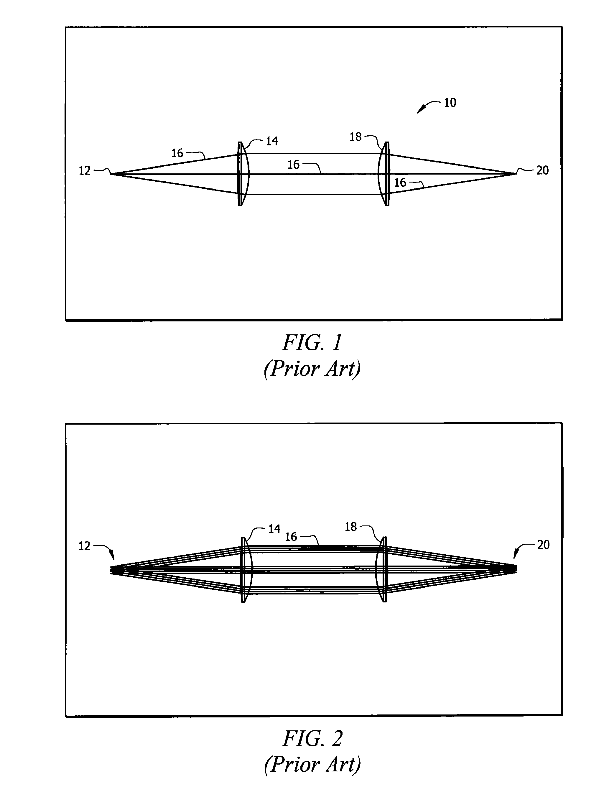
[0042]FIG. 1 is a diagrammatic representation of a conventional arrangement of lenses, denoted as a whole by the reference numeral 10.

[0043]More particularly, FIG. 1 depicts a high power fiber laser light emitted from the output of a fiber 12. Lens 14 collimates light 16 and lens 18 refocuses the light onto focal point 20 that is formed on the surface of a material to be cut, drilled, scribed, marked, welded or otherwise treated. Both lenses are made from high quality fused silica.

[0044]FIG. 2 depicts the FIG. 1 lenses but a multi-thermal configuration has been set up where lenses 14 and 18 are at ambient temperature of 25° C., followed by increase to 50° C., 75° C. and 125° C. respectively. Focus 20 shifts towards said lens due to the temperature increase. Each configuration is overlaid with an offset of two millimeters (2 mm) to show the variation in focus as the temperature is increased.

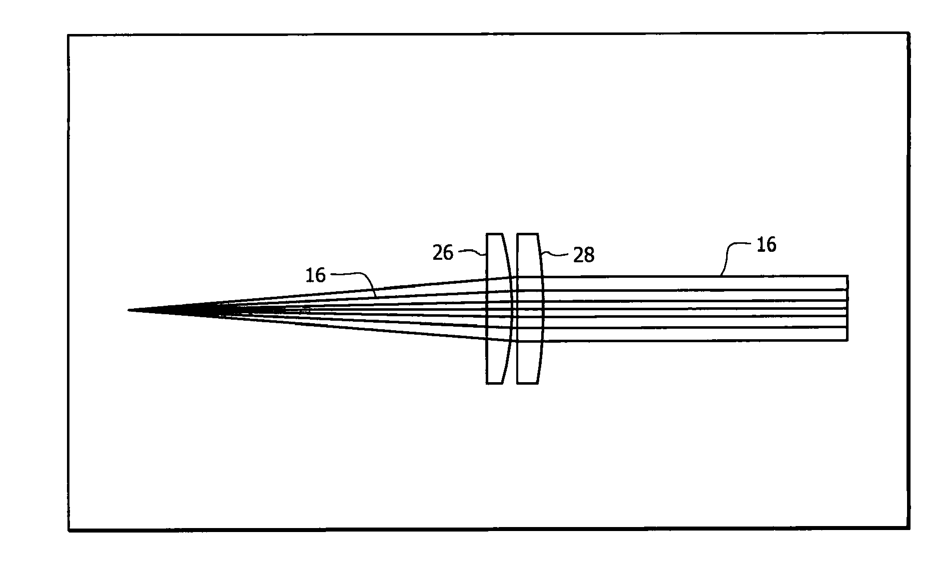
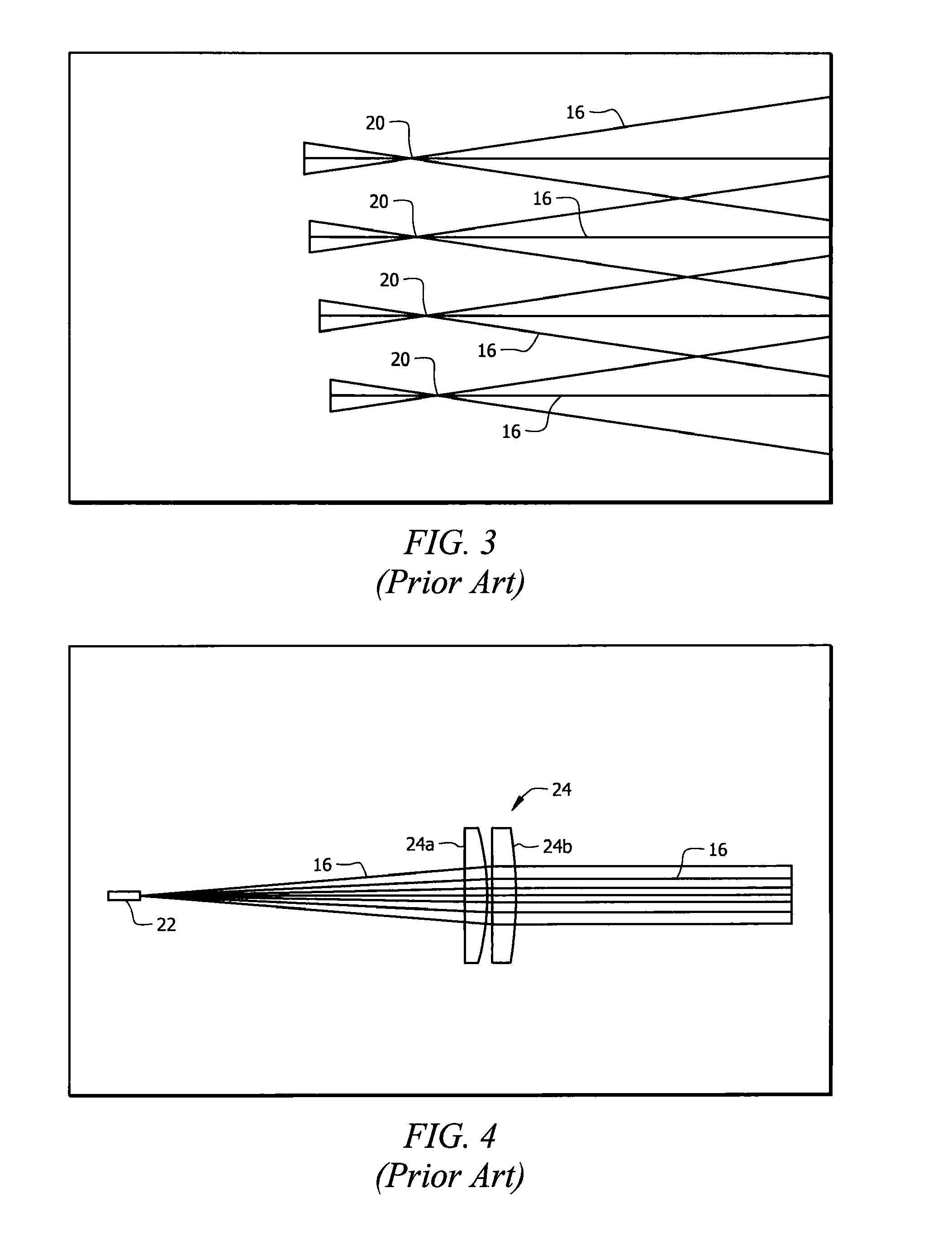
[0045]FIG. 3 is an enlarged view of the focus of FIG. 2. The focus shift from the ambient cond...


PUM


Abstract

A method for thermally compensating lenses in an optical system for high power lasers includes the steps of providing a fused silica lens to collimate a high power laser beam and positioning that lens in collimating relation to the laser beam. A focusing lens assembly is provided to focus the collimated laser beam and is positioned in focusing relation to the collimated laser beam. At least one lens having a negative dn/dT to offset a heat-induced change in index of refraction of the fused silica lens is included as a part of the collimating lens assembly and as a part of the focusing lens assembly. The lens having a negative dn/dT is selected from a group of glasses having a negative dn/dT. The power of the lenses is balanced with an offsetting negative dn/dT so that the optical system maintains its focus over a wide temperature range.

Description

BACKGROUND OF THE INVENTION[0001]1. Field of the Invention[0002]This invention relates, generally, to the art of lasers. More particularly, it relates to a lens for high power lasers.[0003]2. Description of the Prior Art[0004]One or more high quality fused silica lenses are used to focus high power fiber lasers in excess of one kilowatt (1 kW). More specifically, at least one high quality fused silica lens is used to collimate laser light emitted from a fiber laser where the fiber ranges in diameter from 50 microns to over 300 microns. After it has been collimated, the light is directed to a focusing lens assembly made of one or more high quality fused silica lenses that focus the light on to a surface to be cut, drilled, scribed, marked or welded.[0005]Although the fused silica lens material is highly transmissive, some radiation is either absorbed or scattered within the lens, causing the lens to heat up. All optical glass materials have certain thermal properties that change the ...

Claims


Application Information

Patent Timeline
Patent Type & Authority Applications(United States)
IPC IPC(8): G02B27/30G02B1/00
CPCH01S3/005G02B7/028H01S3/10H01S3/04
Inventor SCAGGS, MICHAEL J.
Owner HAAS LASER TECH
Why Eureka
Try Eureka