Resonant converting device, and control module and method for controlling a resonant converter

a resonant converter and converting device technology, applied in the direction of dc-dc conversion, power conversion systems, climate sustainability, etc., can solve the problems of affecting the use of llc resonant converters, low linearity, and large current that may damage electronic components

Active Publication Date: 2011-10-13
LITE ON TECH CORP +1
View PDF4 Cites 9 Cited by
  • Summary
  • Abstract
  • Description
  • Claims
  • Application Information

AI Technical Summary

Benefits of technology

[0007]Therefore, an object of the present invention is to provide a method for controlling operation of a resonant converter capable of current-limiting when the resonant converter is overloaded or when an output of the resonant converter device is short-circuited.
[0009]Another object of the present invention is to provide a method for controlling operation of a resonant converter capable of enhancing linearity of an output voltage generated during the soft-start stage of the resonant converter.
[0011]Yet another object of the present invention is to provide a control module capable of enhancing linearity of an output voltage generated during the soft-start stage of a resonant converter.
[0017]A further object of the present invention is to provide a resonant converting device capable of current-limiting when overloaded or when an output of the resonant converting device is short-circuited.

Problems solved by technology

When the LLC resonant converter 900 is connected to a load RL that is excessively large or is shorted-circuited, the LLC resonant converter 900 will output a large current that may damage electronic components.
Furthermore, during the soft-start stage, the output voltage Vo generated by the LLC resonant converter 900 has low linearity, which hinders the use of the LLC resonant converter 900 in some applications such as servers.
Moreover, use of the current-limiting circuit 910 does not improve linearity of an output voltage Vo of the LLC resonant converter 900′ during the soft-start stage of the LLC resonant converter 900′.

Method used


Image

  • Resonant converting device, and control module and method for controlling a resonant converter
  • Resonant converting device, and control module and method for controlling a resonant converter
  • Resonant converting device, and control module and method for controlling a resonant converter

Examples


Embodiment Construction

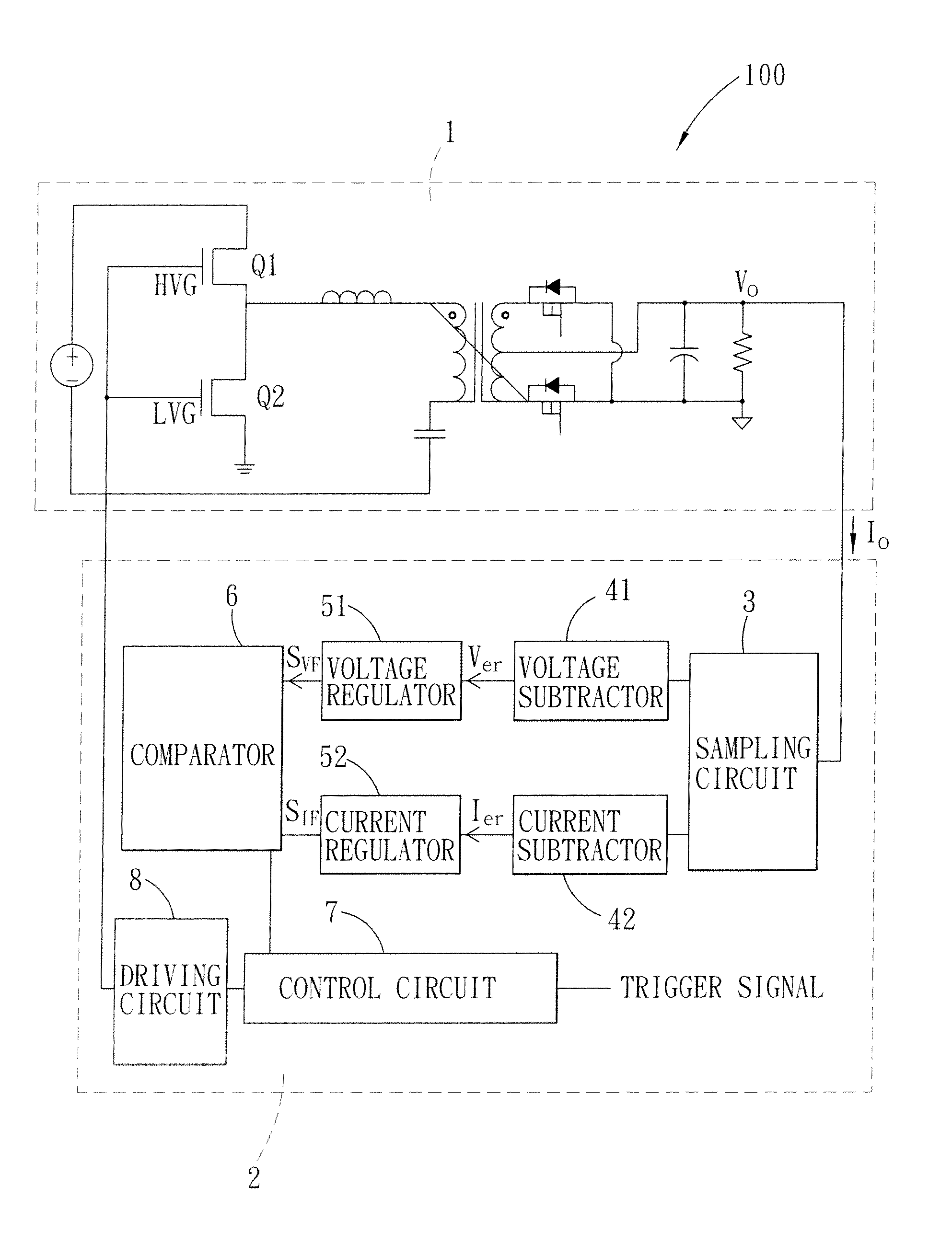
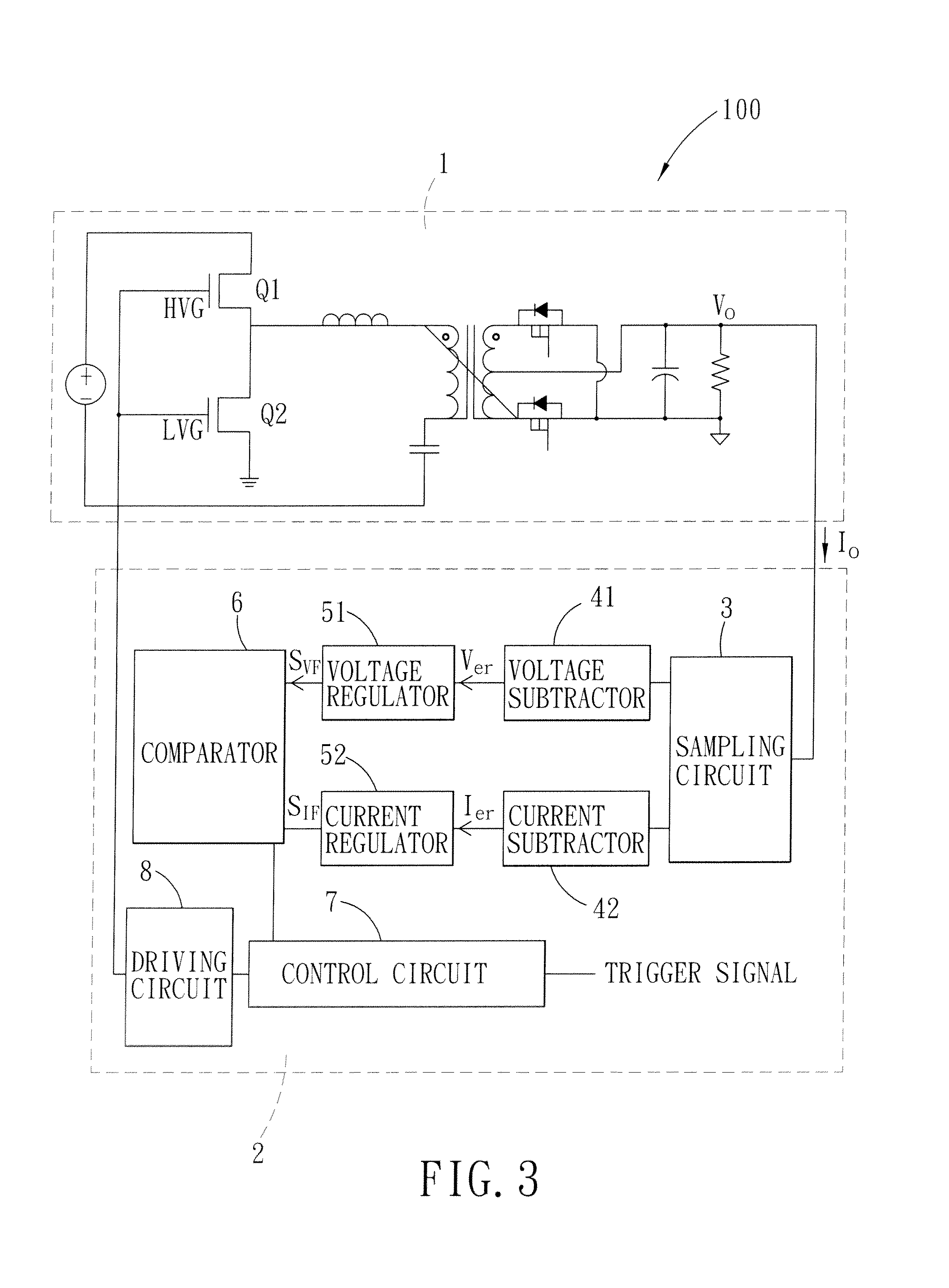
[0032]Referring to FIG. 3, the preferred embodiment of a resonant converting device 100 according to the present invention includes a resonant converter 1 and a control module 2 that is coupled to the resonant converter 1 for controlling an output voltage Vo and an output current Io to be outputted to a load RL by the resonant converter 1. The resonant converting device 100 is applicable to servers, workstations, communication devices, desktop computers, gaming consoles, flat panel televisions, etc. In the present embodiment, the resonant converter 1 is a half-bridge LLC resonant converter coupled to the control module 2 to form a closed loop, and includes first and second power switches Q1, Q2.

[0033]The control module 2 includes a sampling circuit 3, a voltage subtractor 41, a voltage regulator 51, a current subtractor 42, a current regulator 52, a comparator 6, a control circuit 7, and a driving circuit 8. In the present embodiment, the voltage regulator 51 and the current regulat...


PUM


Abstract

A method for controlling operation of a resonant converter is to be implemented by a control module that generates a drive signal for controlling a power switch of the resonant converter to thereby control an output voltage and an output current provided by the resonant converter to a load. The method includes: (A) configuring the control module to determine if the load is operating in a first mode or a second mode; (B) configuring the control module to generate the drive signal according to the output voltage when the control module determines that the load is operating in the first mode; and (C) configuring the control module to generate the drive signal according to the output current when the control module determines that the load is operating in the second mode.

Description

CROSS-REFERENCE TO RELATED APPLICATION[0001]This application claims priority of Chinese Application No. 201010149611.4, filed on Apr. 7, 2010.BACKGROUND OF THE INVENTION[0002]1. Field of the Invention[0003]The present invention relates to a control method, more particularly to a method for controlling a resonant converter.[0004]2. Description of the Related Art[0005]Shown in FIG. 1 is a conventional half-bridge LLC resonant converter 900 including first and second power switches Q1, Q2, and operable for generating an output voltage Vo. When the LLC resonant converter 900 is connected to a load RL that is excessively large or is shorted-circuited, the LLC resonant converter 900 will output a large current that may damage electronic components. Furthermore, during the soft-start stage, the output voltage Vo generated by the LLC resonant converter 900 has low linearity, which hinders the use of the LLC resonant converter 900 in some applications such as servers.[0006]Shown in FIG. 2 is...

Claims


Application Information

Patent Timeline
Patent Type & Authority Applications(United States)
IPC IPC(8): H02M3/335
CPCH02M3/33515Y02B70/1475Y02B70/1433H02M3/33592Y02B70/10
Inventor LI, MING-ZHULI, JING-YANZHAO, QING-LINYE, ZHI-HONGZHANG, CHUN-LIN
Owner LITE ON TECH CORP
Why Eureka
Try Eureka