
Grid-connected inverter

Inactive Publication Date: 2011-10-13
FUJI ELECTRIC CO LTD
View PDF1 Cites 35 Cited by
  • Summary
  • Abstract
  • Description
  • Claims
  • Application Information

AI Technical Summary

Benefits of technology

[0028]The grid-connected inverter according to the invention can make a decision of the presence or absence of an abnormality of a contactor by using only a circuit voltage used for operation control. Thus, there is no necessity of additionally providing a specialized unit for detecting the presence or absence of an abnormality of the contactor. Moreover, the presence or absence of an abnormality of the contactor is decided on the basis of a voltage across a charged capacitor rather than a minute current flowing in a filter circuit to avoid miss-detection caused of a noise. Therefore, a grid-connected inverter with high reliability can be provided without causing upsizing and a cost increase of the grid-connected inverter.
[0029]In addition, an abnormality of a contactor can be found before starting the operation of the grid-connected inverter to enable protection of secondary failure and, along with this, enable safer disconnect from the system.

Problems solved by technology

A second problem aspect is the grid-connected inverter that includes a clamping means.

Method used


Image

  • Grid-connected inverter
  • Grid-connected inverter
  • Grid-connected inverter

Examples


Embodiment Construction

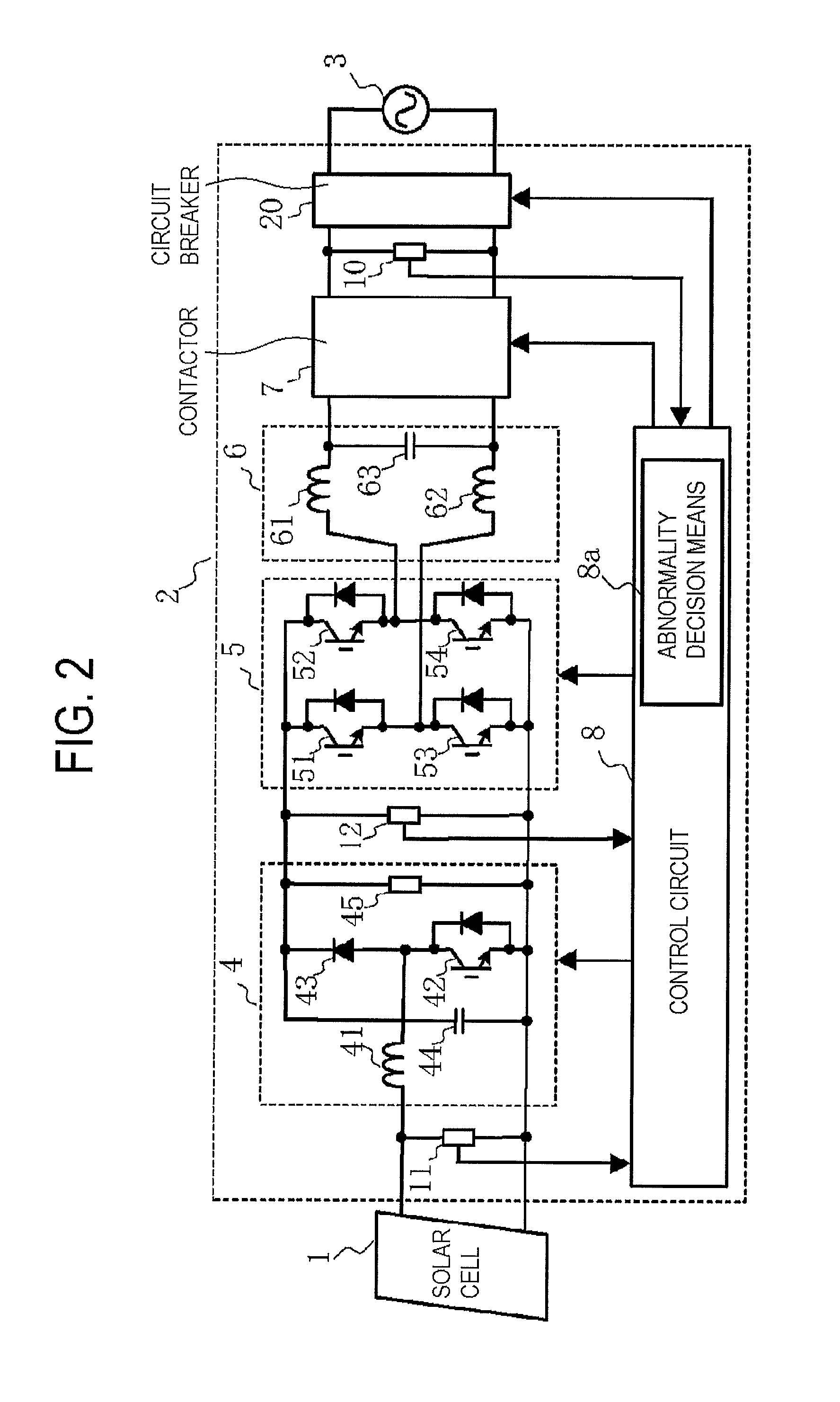
[0037]In the following, embodiments of the invention will be explained in detail on the basis of FIG. 1 to FIG. 5. Here, constituents common to those in the related grid-connected inverter are denoted by the same reference numerals and signs with the explanations thereof will be omitted.

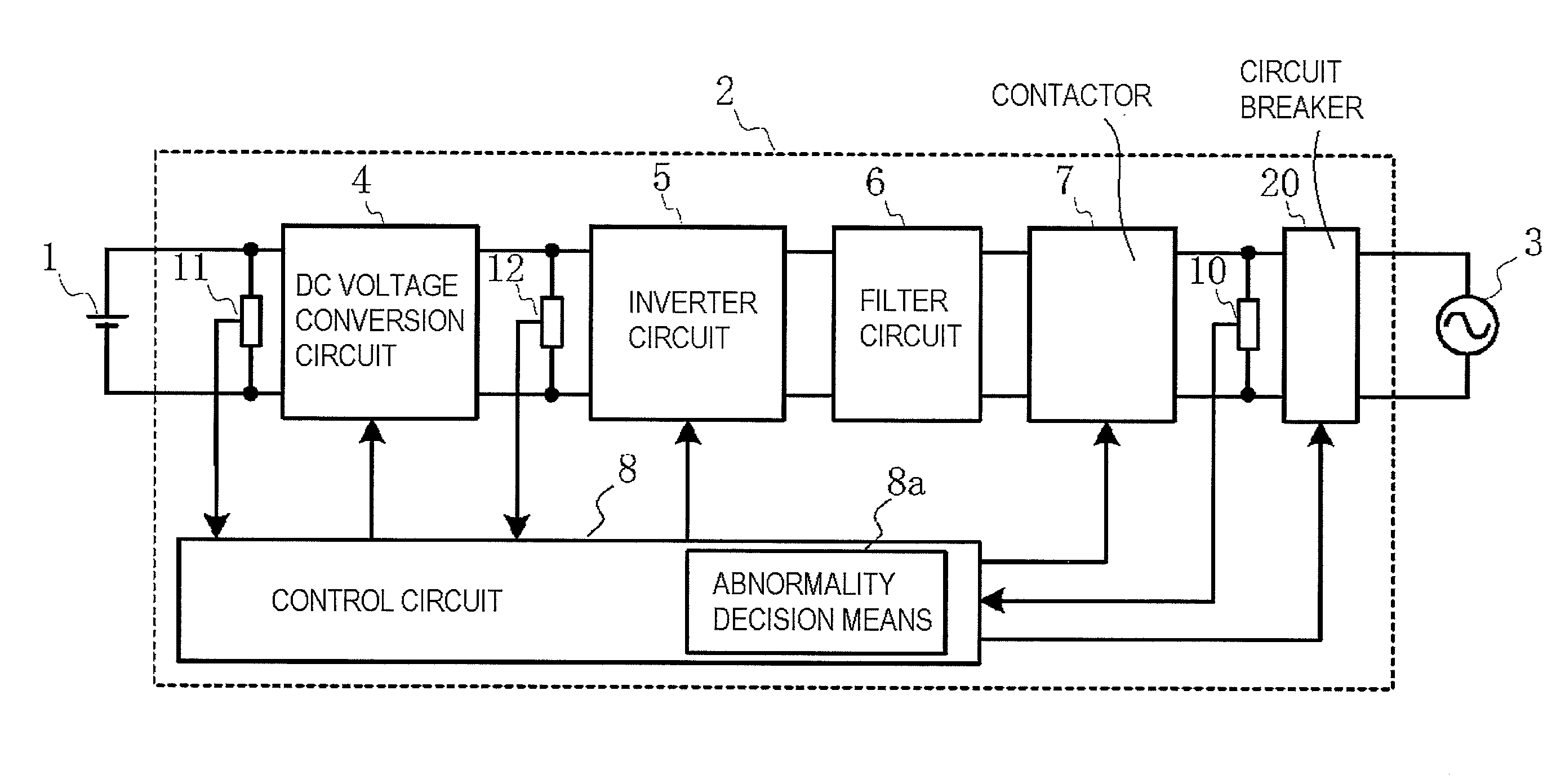
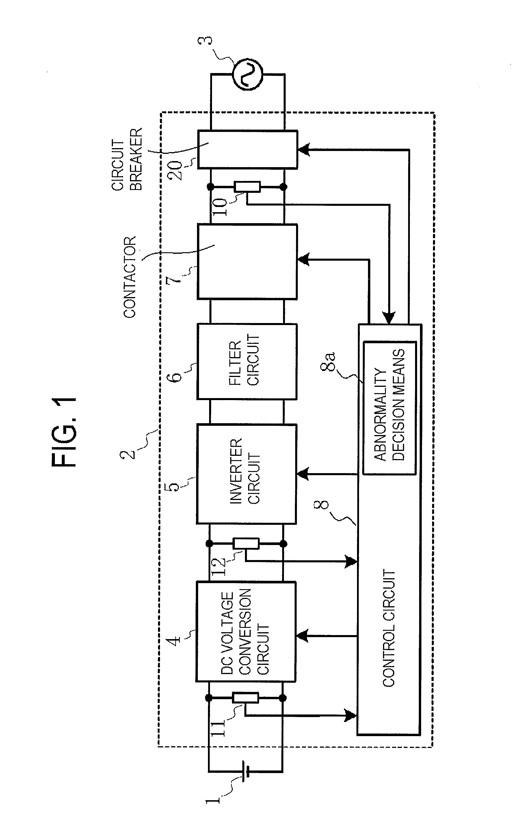
[0038]FIG. 1 is a block diagram showing an outline of a solar cell power generation system as an example of a grid connection system according to the invention. In FIG. 1, a voltage detector 11, a voltage detector 12 and a circuit breaker 20 are clearly shown which are not shown in FIG. 6 and FIG. 7 showing related units.

[0039]The voltage detector 11 is provided between a solar cell 1 and a DC voltage conversion circuit (first electric power conversion circuit) 4 for detecting the generated voltage of the solar cell 1. The voltage detector 12 is provided between the DC voltage conversion circuit 4 and an inverter circuit (second electric power conversion circuit) 5 for detecting the output voltage of...


PUM


Abstract

A grid-connected inverter includes first and second power conversion circuits, a contactor and a control circuit. The first conversion circuit converts a first DC voltage to a second DC voltage. The second conversion circuit converts the second DC voltage to an AC voltage. The contactor connects an output side of the second conversion circuit to a power system. The control circuit includes a decision circuit and controls start and stop operations of the conversion circuits, and opening and closing of the contactor. The decision circuit decides whether a condition of the contactor is abnormal by detecting, after the control circuit controls the contactor to be open, whether or not a value of the second DC voltage is less than a threshold value, and if the value of the second DC voltage is detected to be not less than the threshold value, decides that the condition of the contactor is abnormal.

Description

CROSS-REFERENCE TO RELATED APPLICATION[0001]This application claims priority under 35 U.S.C.§119 from Japanese Patent Application 2010-091120, filed Apr. 12, 2010, the entirety of which is incorporated herein by reference.BACKGROUND OF THE INVENTION[0002]1. Field of the Invention[0003]The present invention relates to a grid-connected inverter that converts DC electric power, generated by solar cells or fuel cells, to AC electric power and is interconnected to a commercial power system.[0004]2. Related Art[0005]Previously, a grid-connected inverter has been provided that converts DC electric power, generated by a solar cell or a fuel cell, to AC electric power and is interconnected to a commercial power system for supplying electric power to loads.[0006]In the following, with reference to FIG. 6 and FIG. 7, a grid connection system including a related interconnection unit will be explained. FIG. 6 is a block diagram showing a solar cell power generation system as a first example of a...

Claims


Application Information

Patent Timeline
IPC IPC(8): H02H7/122
CPCH02H7/122Y02E10/563H02J3/383H02M1/32H02M7/48H02J2300/24H02J3/381Y02E10/56H02M1/322
Inventor FUJII, KANSUKEYAMADA, TOSHIYAKATOH, MASAKI
Owner FUJI ELECTRIC CO LTD
Learn More