

Methods and Apparatus for Managing Error Codes for Storage Systems Coupled with External Storage Systems
a technology of error codes and storage systems, applied in the field of methods and apparatus for managing error codes for storage systems coupled with external storage systems, can solve the problems of low-tier storage not being able to support the added error codes, and achieve the effect of increasing the reliability of the whole system
- Summary
- Abstract
- Description
- Claims
- Application Information
AI Technical Summary
Benefits of technology
Problems solved by technology
Method used
Image

Examples
first embodiment
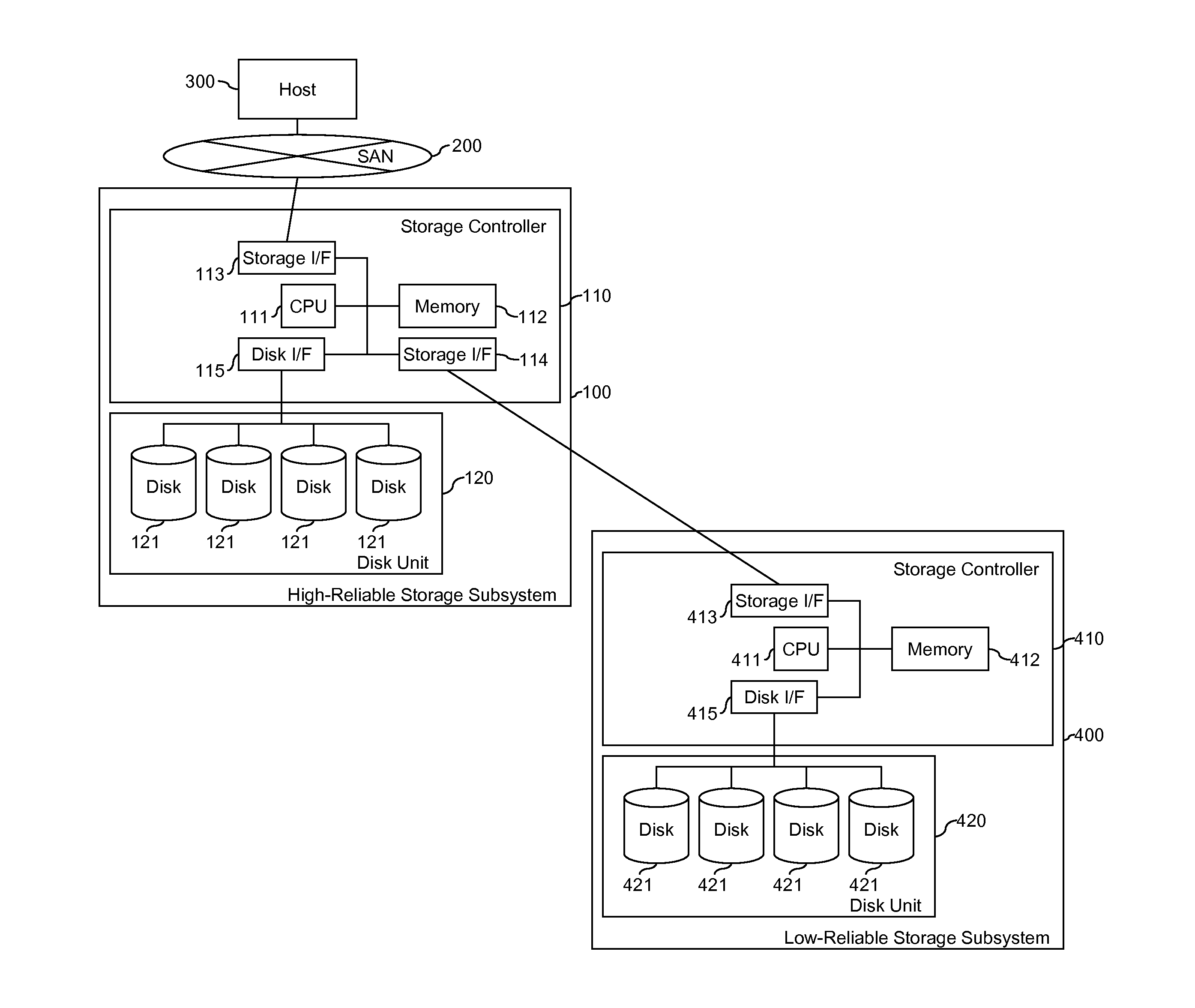
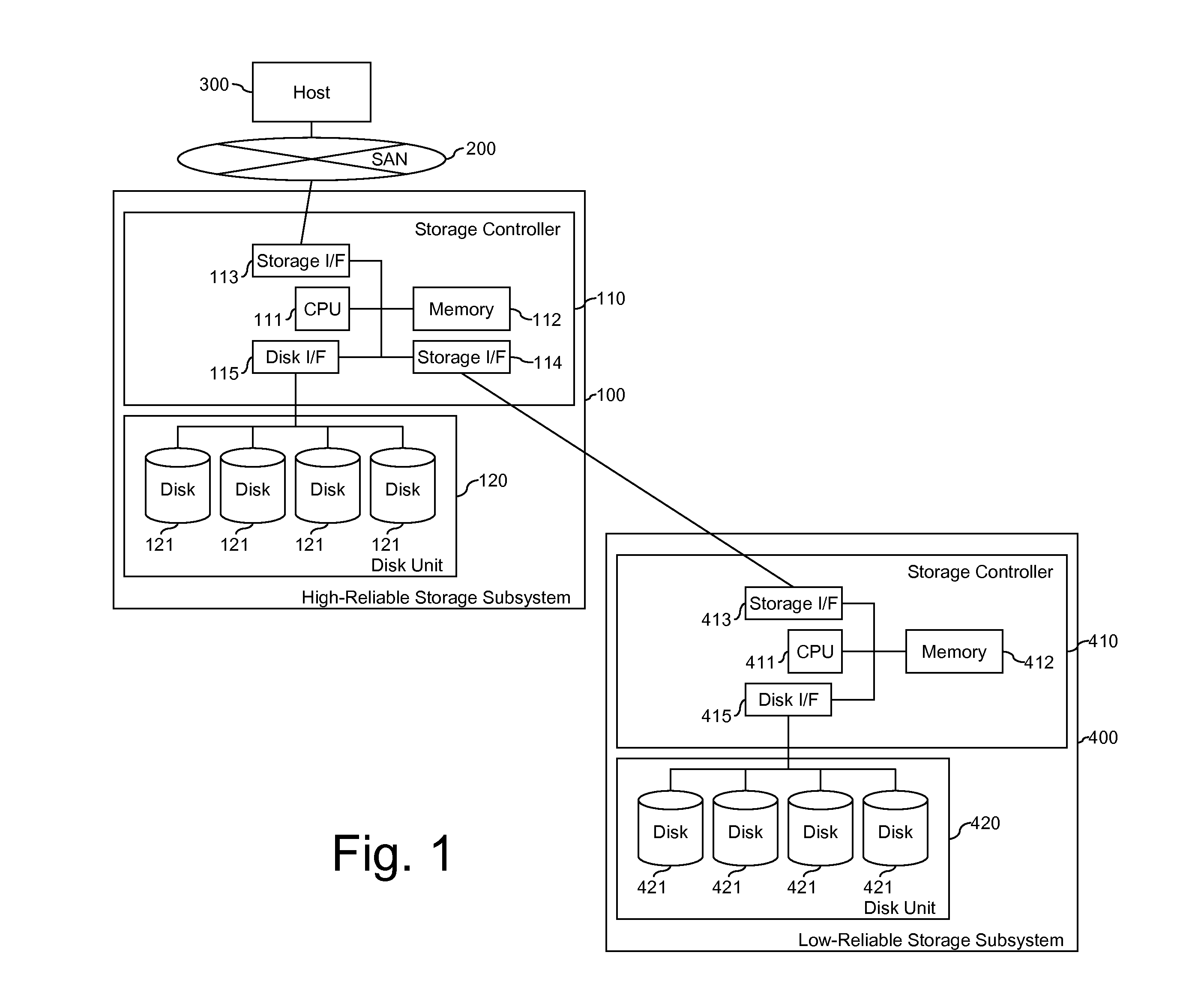
[0034]FIG. 1 illustrates the hardware configuration of a system in which the method and apparatus of the invention may be applied. A storage subsystem 100 is connected via a SAN (storage area network) 200 to a host computer 300. The storage subsystem 400 is connected to the storage subsystem 100 via Fibre Channel (FC). The storage subsystem 100 receives I / O commands from the host computer 200 and provides storage volumes to the host computer 200 using storage devices 121, 421 in both storage subsystems 100, 400. The storage subsystem 100 has a higher data reliability than the storage subsystem 400.
[0035]The storage subsystem 100 has a storage controller 110 that includes a CPU 111, a memory 112, storage interfaces 113, 114, and disk interface 115. The CPU 111 controls the storage subsystem 100, and reads programs and tables from the memory 112. The memory 112 stores the programs and tables. The storage interface 113 connects with a host computer 300 via a storage network 200. The st...
second embodiment
[0054]While in the first embodiment the Storage Controller 110 in the High Reliable Storage Subsystem 100 retrieves the data required to generate the correct data from the Low Reliable Storage Subsystem 400, the second embodiment demonstrates method to generate the correct data by the Storage Controller 410 of the Low Reliable Storage Subsystem 400. Only the differences with the first embodiment will be explained by using FIGS. 20 to 22.
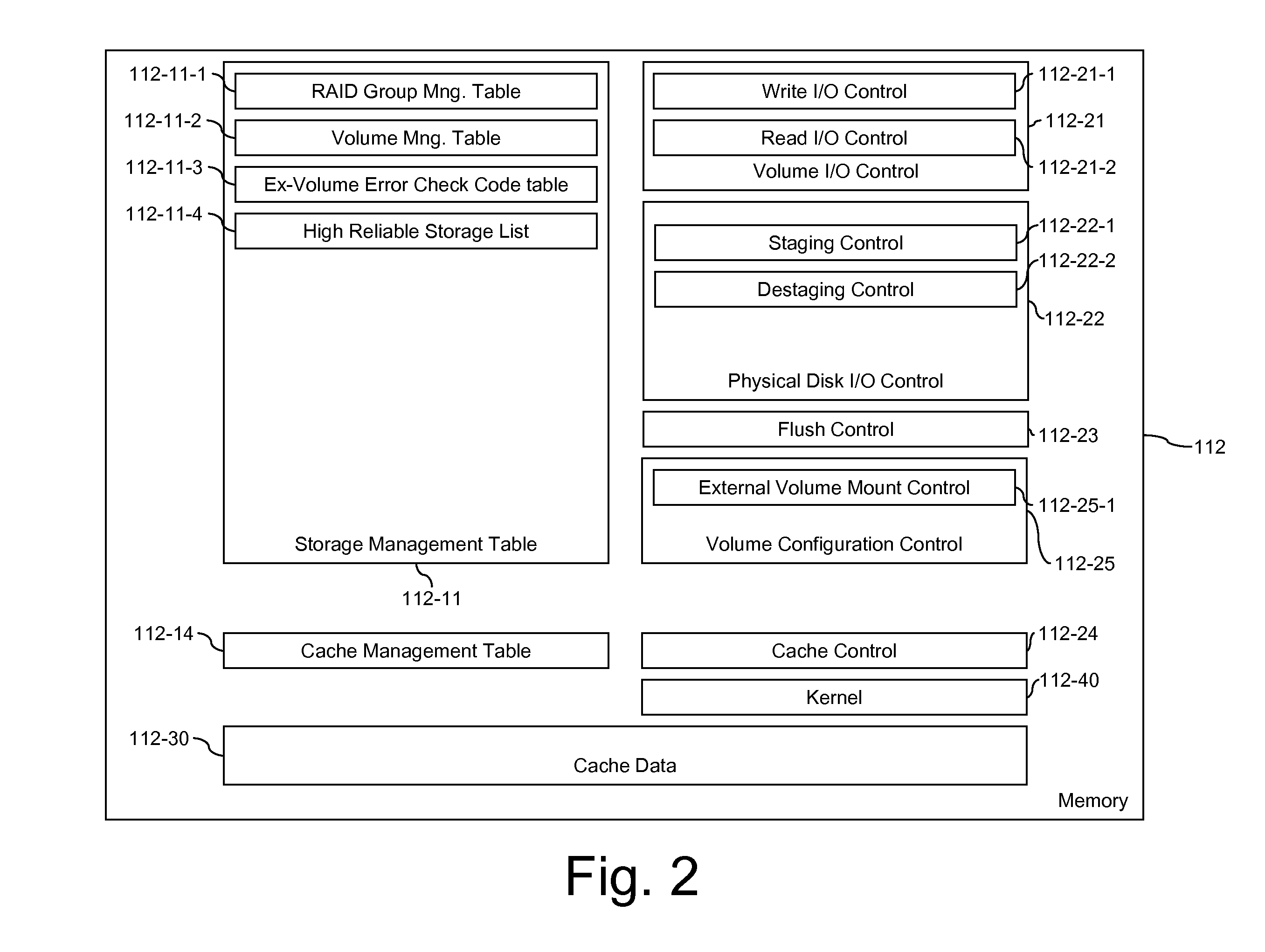
[0055]FIG. 20 illustrates an example of a process flow of the Staging Control 112-22-1 in the memory 112 of FIG. 2. The program starts at 112-22-1-1. In step 112-22-1-2, the program refers to Volume Management Table 112-11-2 and RAID Group Management Table 112-11-1 to determine the physical disk and address of the data. In step 112-22-1-3, the program requests to read data from the slot of disk 121 and store it to the buffer. In step 112-22-1-4, the program checks whether the data is stored in the external volume allocated by relatively low reliabili...
third embodiment
[0060]In this embodiment, the storage system has more than two Low Reliable Storage Subsystems 400, which duplicate data is stored. Thus, if the data read from one of the Low Reliable Storage Subsystem 400 has corrupted, the data is read from the other Low Reliable Storage Subsystem 400. Only the differences with the first embodiment will be explained by using FIGS. 24 to 28.
[0061]FIG. 24 illustrates the hardware configuration of a system in which the method and apparatus of the invention may be applied. A storage subsystem 100 is connected via a SAN (storage area network) 200 to a host computer 300. The storage subsystem 400 is connected to the Storage subsystem 100 via Fibre Channel (FC). The storage subsystem 100 receives I / O commands from the host computer 200 and provides storage volumes to the host computer 200 using storage devices 121, 421 in both storage subsystems 100, 400. The storage subsystem 100 has higher data reliability than the storage subsystem 400. For example, s...
PUM
 Abstract
Description
Claims
Application Information